
High-frequency vibrator control system

A high-frequency vibrator and control system technology, applied in the direction of manufacturing tools, auxiliary molding equipment, ceramic molding machines, etc., can solve the problems of high labor intensity, large vibration, and mold explosion for operators

Active Publication Date: 2019-09-20
SANCHU OF CHINA RAILWAY TUNNEL GROUP
View PDF7 Cites 1 Cited by
  • Summary
  • Abstract
  • Description
  • Claims
  • Application Information

AI Technical Summary

Problems solved by technology

The concrete pouring of the second lining of the tunnel needs to be used in conjunction with the attachment type and the insertion type vibrator. The traditional attachment type vibrator adopts a set of control system. During the vibration process, the vibration of the trolley is relatively large, which is easy to cause the hidden danger of mold explosion. The practicability is not strong, the vibrating efficiency is low, and a lot of labor is required
It is difficult to control multiple vibrators accurately, the labor intensity of the operators is high, and the working environment is harsh. Because of the difference in timing and operation level of tamping operations, it often results in missed tamping, over tamping or mistakes, resulting in sanding, blowholes, and even There are cracks, which directly cause defects on the molding surface, and the quality fluctuates greatly

Method used


Image

  • High-frequency vibrator control system
  • High-frequency vibrator control system

Examples


Embodiment Construction

[0019] The implementation mode of the present invention is illustrated by specific specific examples below, and those who are familiar with this technology can easily understand other advantages and effects of the present invention from the contents disclosed in this description. Obviously, the described embodiments are a part of the present invention. , but not all examples. Based on the embodiments of the present invention, all other embodiments obtained by persons of ordinary skill in the art without making creative efforts belong to the protection scope of the present invention.

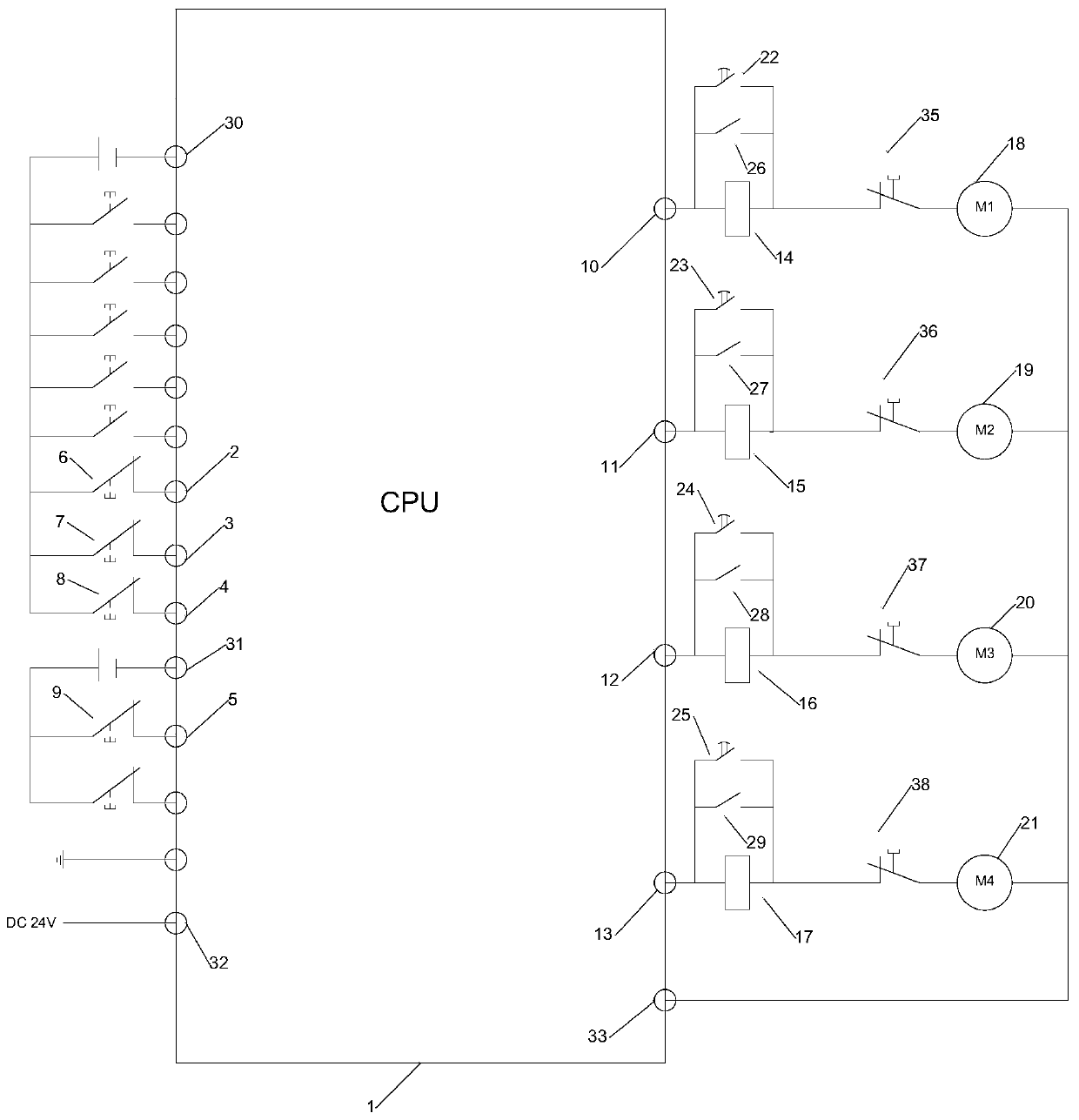
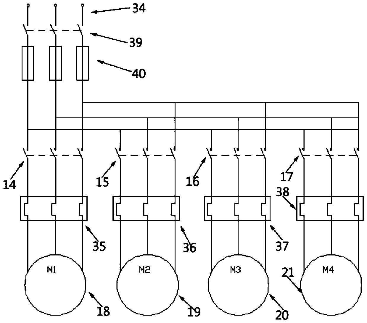
[0020] see figure 1 and figure 2 , providing a high-frequency vibrator control system, including a control assembly and a vibration assembly, the control assembly includes a central processing unit 1, and the central processing unit 1 is provided with a first input pin 2, a second input pin 3, The third input pin 4 and the fourth input pin 5, the first input pin 2 is connected with a first nor...


PUM


Abstract

The invention discloses a high-frequency vibrator control system. A first input pin is connected with a first normally closed switch; a second input pin is connected with a second normally closed switch; a third input pin is connected with a third normally closed switch; a fourth input pin is connected with a fourth normally closed switch; a first output pin is connected with a first contactor; a second output pin is connected with a second contactor; a third output pin is connected with a third contactor; a fourth output pin is connected with a fourth contactor; the first contactor is connected with a first time relay in parallel; the second contactor is connected with a second time relay in parallel; the third contactor is connected with a third time relay in parallel; the fourth contactor is connected with a fourth time relay in parallel; the first time relay is connected with a first intermediate relay in parallel; the second time relay is connected with a second intermediate relay in parallel; the third time relay is connected with a third intermediate relay in parallel; and the fourth time relay is connected with a fourth intermediate relay in parallel. According to the system, remote multi-terminal control of a vibrator is achieved, and the vibrating efficiency and accuracy are improved.

Description

technical field [0001] Embodiments of the present invention relate to the technical field of vibrators, and in particular to a high-frequency vibrator control system. Background technique [0002] At present, when using a concrete mixer to mix well-mixed concrete to pour components, the air bubbles in it must be removed by a concrete vibrator and tamped to make the concrete densely combined and eliminate the honeycomb pitting of the concrete, so as to improve its strength and ensure that the concrete component quality. When the concrete vibrator is working, the internal friction and adhesion between the particles inside the concrete are drastically reduced, and the concrete is in a heavy liquid state. The aggregates slide against each other and rearrange, the gaps between the aggregates are filled with mortar, and the air bubbles are squeezed out, thus achieving the effect of tamping. [0003] At present, during the tunnel reconstruction process, the quality of tamping dir...

Claims


Application Information

Patent Timeline
Patent Type & Authority Applications(China)
IPC IPC(8): B28B1/04B28B1/087B28B17/00
CPCB28B1/045B28B17/0072
Inventor 彭兴强李友坤刘志新剡国强高勇鲁燕群薛潮
Owner SANCHU OF CHINA RAILWAY TUNNEL GROUP
Learn More