
Railway loading, unloading and transferring device

A transfer device, railway technology, applied in the direction of lifting device, etc., can solve the problem that the lifting device is not suitable for loading and unloading and transfer, and achieve the effect of convenient loading, unloading and transfer.

Active Publication Date: 2019-09-20
ZHENGZHOU RAILWAY VOCATIONAL & TECH COLLEGE
View PDF10 Cites 1 Cited by
  • Summary
  • Abstract
  • Description
  • Claims
  • Application Information

AI Technical Summary

Problems solved by technology

[0002] The application number is CN201620428262.2, which discloses a lifting device for lifting the blind plate of the loading and unloading arm. The lifting assembly of the rotating assembly, the rotating assembly includes a rotating rod and a sleeve sleeved on the rotating rod, the lifting assembly includes a lifting rod, a lifting ring, a wire rope and lifting lugs, and the lifting rod is rotatably connected The rotating rod, the lifting ring is rotatably connected to the lower end of the lifting rod, the steel wire rope passes through the lifting ring, and the two ends of the steel wire rope are respectively connected to a lifting lug; the utility model provided for The lifting device for lifting the blind plate of the loading and unloading arm, the opening and closing operation of the blind plate is convenient, it replaces the traditional way of manually installing and removing the blind plate, which reduces the labor burden of the staff and improves the working efficiency at the same time. But the lifting device is not suitable Loading, unloading and transshipment on rail

Method used


Image

  • Railway loading, unloading and transferring device
  • Railway loading, unloading and transferring device
  • Railway loading, unloading and transferring device

Examples


specific Embodiment approach 1

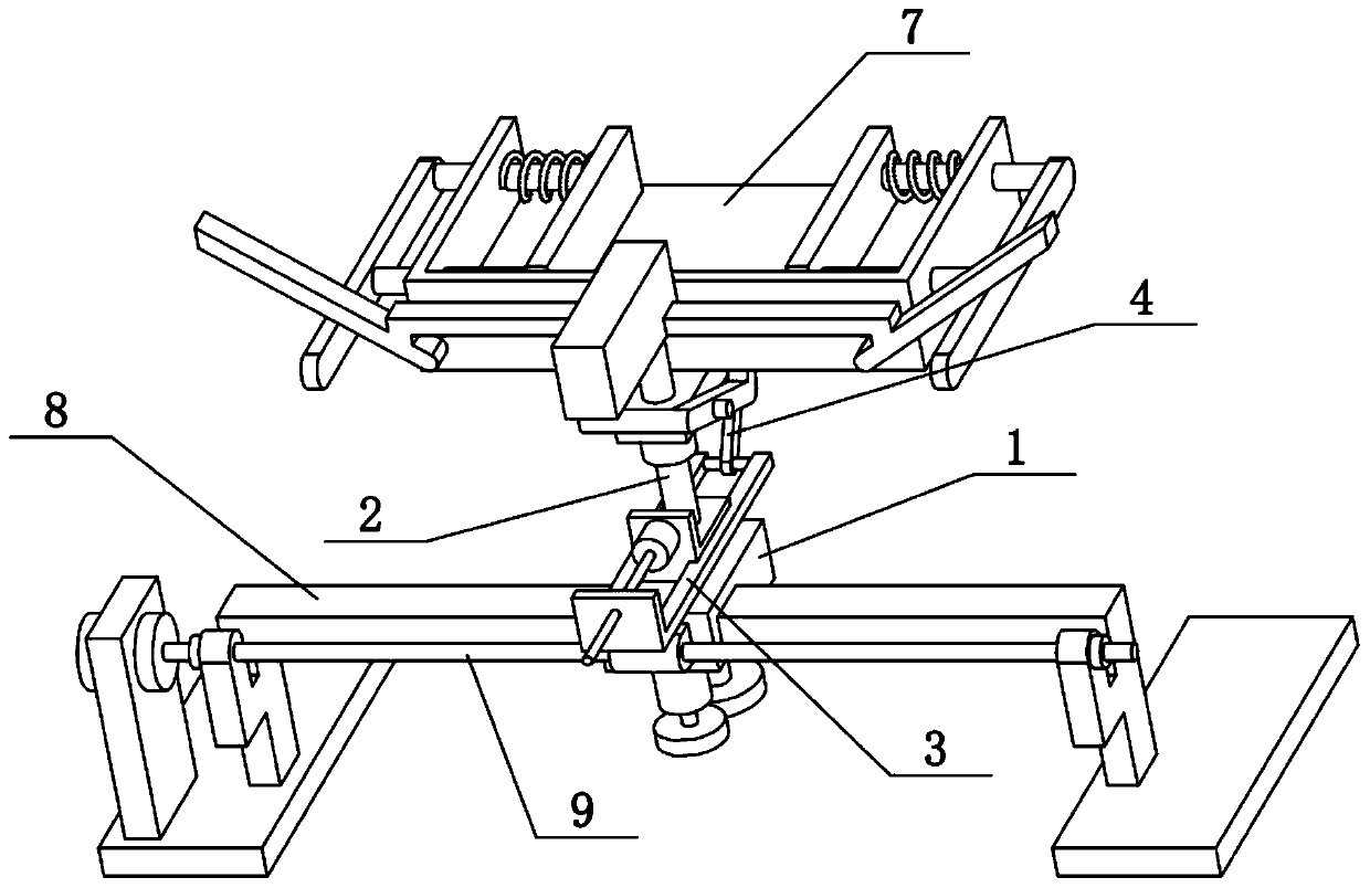
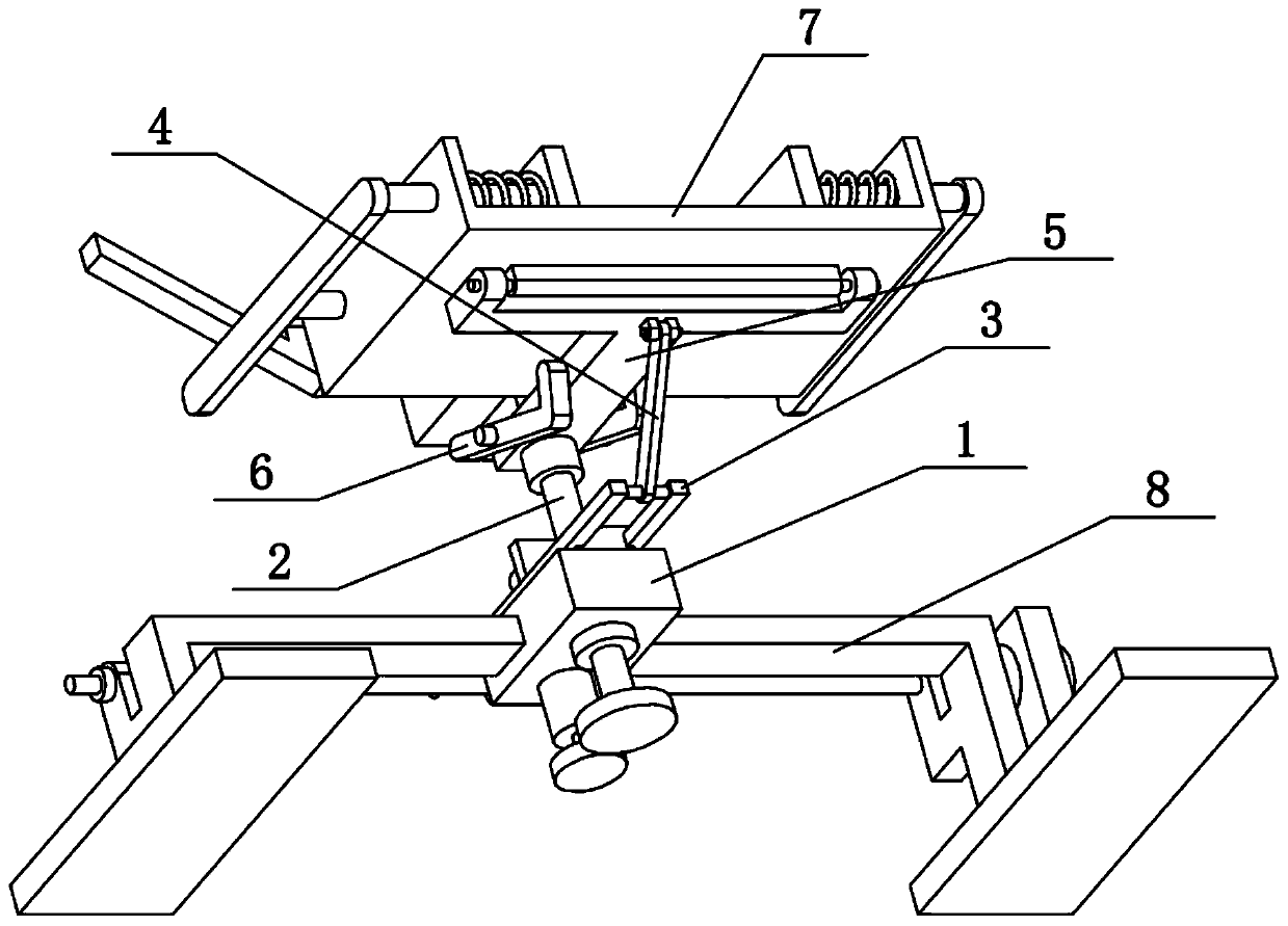
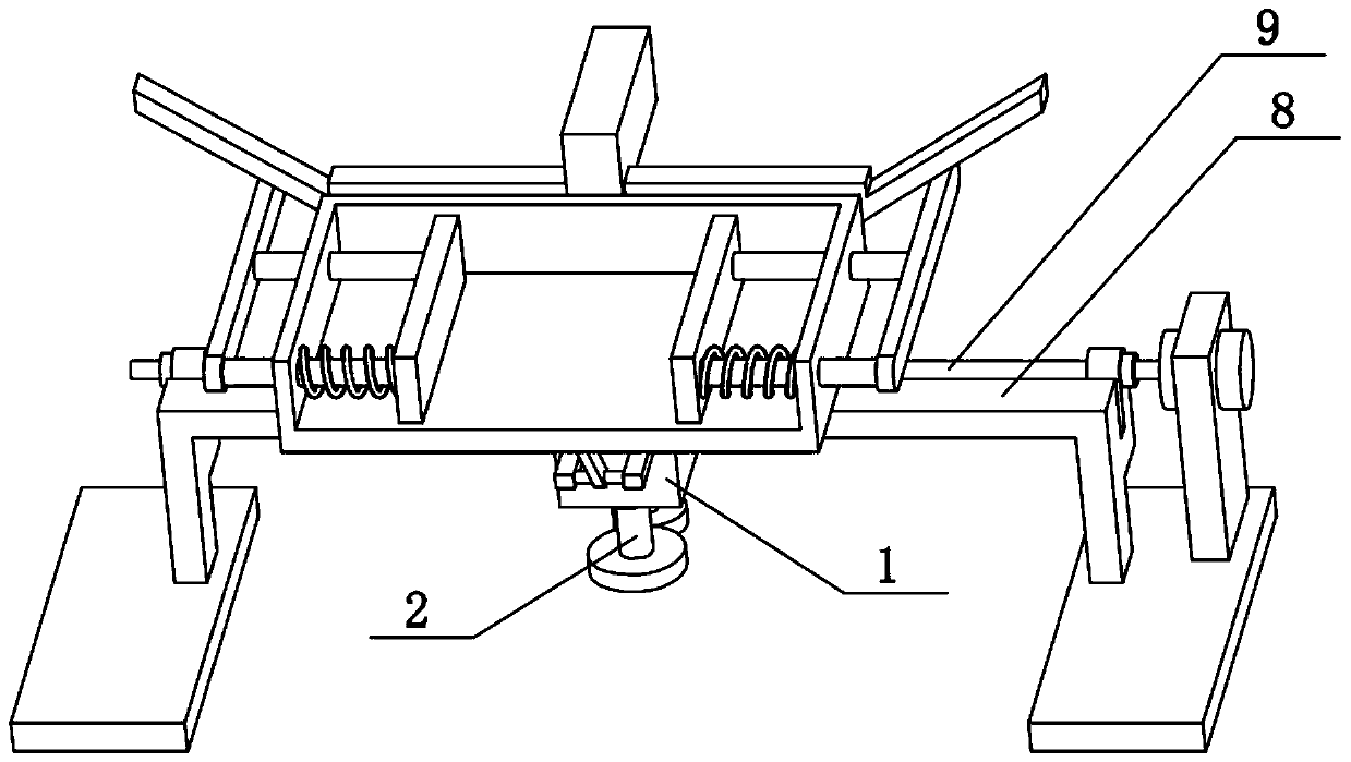
[0036] Combine below Figure 1-14 Describe this embodiment, the present invention relates to the railway field, more specifically a railway loading and unloading transfer device, including a sliding seat 1, a vertical shaft 2, a pallet 5, a hinged seat 51, a sliding cylinder 52, a loading and unloading box 7 and a hinged joint The bump 71, the present invention can lift the goods from low to high on the railway, and after lifting, the loading and unloading box 7 unloads the goods, which is convenient for loading, unloading and transshipment on the railway.

[0037] The vertical shaft 2 is rotatably connected to the sliding seat 1, the front side of the supporting plate 5 is provided with a sliding cylinder 52, and the sliding cylinder 52 is slidably connected on the vertical shaft 2, and the rear side of the supporting plate 5 is provided with a hinged seat 51, The lower side of the loading and unloading box 7 is provided with a hinged projection 71 , which is hingedly connect...

specific Embodiment approach 2

[0039] Combine below Figure 1-14 To illustrate this embodiment, the railway loading, unloading and transshipment device also includes a fixed block 21, a parallel rod 3, a threaded orifice plate 31 and an oblique connecting rod 4, the vertical shaft 2 is fixedly connected with the fixed block 21, and the parallel rod 3 is provided with two , the two parallel rods 3 are respectively slidably connected to the left and right sides of the fixed block 21, the front ends of the two parallel rods 3 are fixedly connected with a threaded orifice plate 31, and the lower ends of the oblique connecting rods 4 are hingedly connected to the two parallel rods 3 Between the rear ends, the upper end of the oblique connecting rod 4 is hingedly connected to the underside of the supporting plate 5 . The two parallel rods 3 can slide back and forth on the fixed block 21. When the two parallel rods 3 slide back and forth, the inclined connecting rod 4 drives the supporting plate 5 and the sliding ...

specific Embodiment approach 3

[0041] Combine below Figure 1-14 Describe this embodiment, described railway loading and unloading transshipment device also comprises motor II24 and lead screw I25, and the front side of fixed block 21 is fixedly connected with motor II24, and the output shaft of motor II24 is fixedly connected with lead screw I25, and lead screw I25 is threaded Cooperate with the threaded orifice plate 31. When the output shaft of the motor II24 rotates, it can drive the lead screw I25 to rotate around its own axis, and the rotation of the lead screw I25 around its own axis can drive the threaded orifice plate 31 to slide back and forth, thereby realizing the control of the two parallel rods 3 on the fixed block 21. Swipe up and down.


PUM


Abstract

The invention relates to the field of railways, in particular to a railway loading, unloading and transferring device which comprises a sliding base, a vertical shaft, a carrier plate, a hinge base, a sliding cylinder, a loading and unloading box and a hinge protruding block. According to the railway loading, unloading and transferring device, goods can be lifted from low to high on a railway, after the goods are lifted, the loading and unloading box unloads the goods, and loading, unloading and transferring can be carried out on the railway conveniently. The vertical shaft is connected to the sliding base in a rotating manner. The sliding cylinder is arranged on the front side of the carrier plate. The sliding cylinder is connected to the vertical shaft in a sliding manner. A hinge base is arranged on the rear side of the carrier plate. The hinge protruding block is arranged on the lower side of the loading and unloading box, the hinge protruding block is connected to the hinge base in a hinged manner, and the loading and unloading box is arranged at the upper end of the carrier plate.

Description

technical field [0001] The invention relates to the field of railways, in particular to a railway loading and unloading transfer device. Background technique [0002] The application number is CN201620428262.2, which discloses a lifting device for lifting the blind plate of the loading and unloading arm. The lifting assembly of the rotating assembly, the rotating assembly includes a rotating rod and a sleeve sleeved on the rotating rod, the lifting assembly includes a lifting rod, a lifting ring, a wire rope and lifting lugs, and the lifting rod is rotatably connected The rotating rod, the lifting ring is rotatably connected to the lower end of the lifting rod, the steel wire rope passes through the lifting ring, and the two ends of the steel wire rope are respectively connected to a lifting lug; the utility model provided for The lifting device for lifting the blind plate of the loading and unloading arm, the opening and closing operation of the blind plate is convenient, ...

Claims


Application Information

Patent Timeline
Patent Type & Authority Applications(China)
IPC IPC(8): B66F9/02
CPCB66F9/02
Inventor 张翠赵明丽周钰爽原方方马芳
Owner ZHENGZHOU RAILWAY VOCATIONAL & TECH COLLEGE
Learn More