
Permeable pavement device and corresponding water drainage method thereof

A technology of permeable pavement and permeable holes, which is applied to pavement details, roads, side ditch/curbstone, etc., can solve problems such as low compressive strength, and achieve the effect of improving the service life of pavement, reducing pressure and reducing the occurrence of blockage.

Active Publication Date: 2019-09-20
BEIJING UNIV OF CIVIL ENG & ARCHITECTURE
View PDF9 Cites 6 Cited by
  • Summary
  • Abstract
  • Description
  • Claims
  • Application Information

AI Technical Summary

Problems solved by technology

The permeable pavement framework and permeable pavement have high water permeability, convenient construction and low cost, but their compressive strength is low

Method used


Image

  • Permeable pavement device and corresponding water drainage method thereof
  • Permeable pavement device and corresponding water drainage method thereof
  • Permeable pavement device and corresponding water drainage method thereof

Examples


Embodiment 11

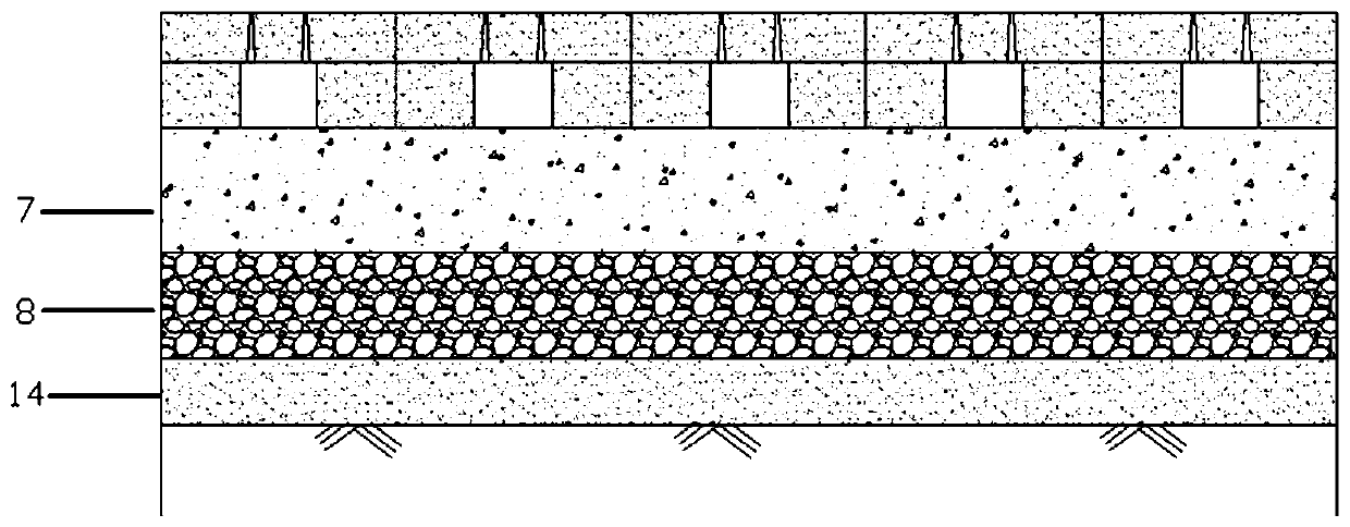
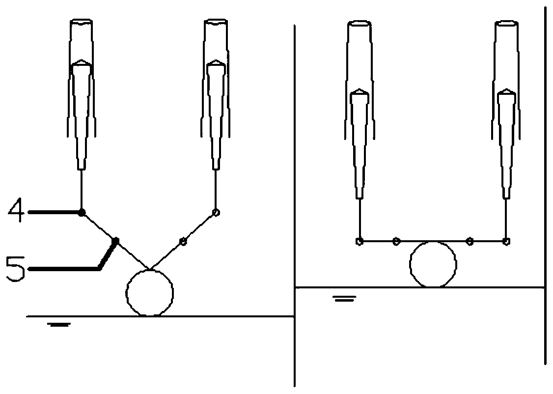
[0048] Embodiment 1.1: A kind of permeable pavement structure, such as Figure 1-Figure 6 As shown, it includes an arrangement of several water storage modules, wherein the water storage module includes two permeable holes 1 with a height of 6 cm, and a water storage cavity 10 with a height of 7 cm is included below the permeable holes 1, and a float 11 is arranged in the water storage cavity 10 , the float 11 is connected to the movable rod 3 through the connecting rod, and the movable column 9 is connected to the top of the movable rod 3, and the movable column 9 is embedded in the permeable hole 1, and the movable column 9 moves up and down in the permeable hole 1 according to different water levels; the permeable hole 1 The upper part includes a strainer 13 .

[0049] A movable rotating shaft 4 is arranged between the connecting rod and the movable rod 3, and the connecting rod includes a fixed rotating shaft 5, so that the connecting rod rotates around the fixed rotating ...

Embodiment 12

[0057] Embodiment 1.2: A kind of permeable pavement structure, such as Figure 8-Figure 12 As shown, it includes an arrangement of several water storage modules, wherein the water storage module includes two water permeable holes 9' with a height of 6cm, and the module between the two water permeable holes 9' also includes a mounting hole, which is equipped with movable The mechanism 1', the movable mechanism 1' includes a large connecting column 10', which is connected with the movable column 4' embedded in the permeable hole 9' through a small connecting column 8', and the large connecting column 10 ', the movable column 4' and the small connecting column 8' form a "mountain"-shaped structure; the upper part of the permeable hole 9' includes a filter screen 2', and the bottom of the small connecting column 8' is a water storage chamber 5'.

[0058] Spring is housed in the water storage cavity 5 ' of the center below of little connecting column 8 ', is convenient to keep cert...


PUM

PropertyMeasurementUnit
Thicknessaaaaaaaaaa

Abstract

The invention provides a permeable pavement device and a corresponding water drainage method thereof. The permeable pavement device comprises at least one water storage module; the upper surface of the water storage module comprises at least two water permeable holes (1); water storage cavities (10) are included under the water permeable holes (1); floaters (11) are arranged in the water storage cavities (10); the floaters (11) are connected with movable columns (9); the movable columns (9) are embedded into the water permeable holes (1); and the movable columns (9) move up and down within the water permeable holes (1) according to different water levels. The permeable pavement device has the main innovation points that the water storage cavities are formed in the water storage module, an upper framework of the water storage module bears a load, and therefore, the purpose of enhancing the strength of a permeable pavement is realized; and as the structure adopts an integrated structure and a design of the water permeable holes, pollutants can be intercepted, the blockage can be reduced as much as possible, and the service life of the pavement is prolonged.

Description

technical field [0001] The invention relates to a permeable pavement structure, which can be used for road construction such as urban sidewalks and carriageways. Background technique [0002] With the rapid economic growth and the acceleration of urbanization, the underlying surface of the city is constantly replaced by buildings and various impermeable roads, making it difficult for precipitation to penetrate into the ground, and the surface runoff formed is easy to accumulate water, and the pavement water generated is not only It affects traffic, and aggravates urban waterlogging, posing a serious threat to people's production and life. [0003] The concept of "sponge city" construction has proposed a solution to the problem of urban waterlogging. Among them, the permeable pavement technology has been rapidly developed and applied on a large scale because it can realize the rapid infiltration of rainwater. However, in actual engineering, it is also faced with the problem...

Claims


Application Information

Patent Timeline
IPC IPC(8): E01C11/22
CPCE01C11/225E01C2201/20
Inventor 李海燕李锦熙张轶慧杨志超
Owner BEIJING UNIV OF CIVIL ENG & ARCHITECTURE
Learn More