
A permeable device for sponge city

A sponge city and urban drainage technology, which is applied to pavement, roads, buildings and other directions paved with prefabricated blocks, can solve the problems of limited rainwater flood discharge capacity, hindering rainwater seepage, road surface water, etc.

Active Publication Date: 2021-04-20
安庆仁创聚源生态环保科技有限公司
View PDF7 Cites 0 Cited by
  • Summary
  • Abstract
  • Description
  • Claims
  • Application Information

AI Technical Summary

Problems solved by technology

[0002] Most of the current urban roads are paved with impermeable pavement, which seriously hinders the infiltration of rainwater, resulting in very limited rainwater drainage through the road surface and flood discharge capacity. When encountering heavy rainfall, large-scale water accumulation will occur on the road surface

Method used


Image

  • A permeable device for sponge city
  • A permeable device for sponge city
  • A permeable device for sponge city

Examples


Embodiment 1

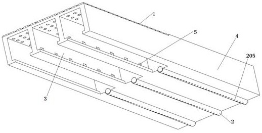
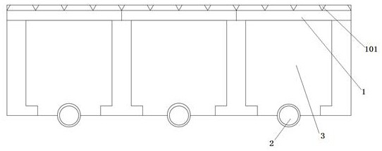
[0058] see Figure 1-10 As shown, the present invention is a permeable device for a sponge city, including a permeable floor tile 1, a permeable pipe 2 and a permeable channel 3;

[0059] The permeable floor tile 1 has a rectangular structure; the upper surface of the permeable floor tile 1 is evenly arrayed with flow channels 101; the flow channel 101 is uniformly provided with permeable holes 102; the permeable holes 102 have a circular frustum structure; the flow channels 101 have an inverted isosceles triangle structure;

[0060] There are permeable floor tiles 1 evenly arrayed on the top of the permeable channels 3; a solid road section 4 is laid between the two permeable channels 3; a permeable pipe 2 is laid in the solid road section 4; the two permeable channels 3 are connected through the permeable pipe 2;

[0061] Water-permeable pipes 201 are evenly arrayed on the bottom of two sides of the permeable pipe; or water-permeable ports 205 are evenly opened on the bottom...

Embodiment 2

[0080] see Figure 1-13 As shown, the present invention is a permeable device for a sponge city, including a permeable floor tile 1, a permeable pipe 2 and a permeable channel 3;

[0081] The permeable floor tile 1 has a rectangular structure; the upper surface of the permeable floor tile 1 is evenly arrayed with flow channels 101; the flow channel 101 is uniformly provided with permeable holes 102; the permeable holes 102 have a circular frustum structure; the flow channels 101 have an inverted isosceles triangle structure;

[0082] There are permeable floor tiles 1 evenly arrayed on the top of the permeable channels 3; a solid road section 4 is laid between the two permeable channels 3; a permeable pipe 2 is laid in the solid road section 4; the two permeable channels 3 are connected through the permeable pipe 2;

[0083] Water-permeable pipes 201 are evenly arrayed on the bottom of two sides of the permeable pipe; or water-permeable ports 205 are evenly opened on the bottom...


PUM


Abstract

The invention discloses a water-permeable device for a sponge city and relates to the technical field of urban road engineering. The invention comprises permeable floor tiles, permeable pipes and permeable channels; the permeable floor tiles have a rectangular structure; the upper surface of the permeable floor tiles is evenly arrayed with flow channels; the flow channels are uniformly provided with permeable holes; the permeable holes are circular table-shaped structures; Permeable floor tiles; a solid road section is laid between two permeable channels; permeable pipes are laid in the solid road section; two permeable channels are connected through permeable pipes; permeable pipes are evenly arrayed at the bottom of the sides around the permeable pipes; or around the permeable pipes Water permeable openings are evenly opened on the bottom of the side. Through the functions of the permeable floor tiles, the permeable pipes and the permeable channels, the present invention has the advantages of significantly improving the water inflow velocity of the permeable floor tiles, strong water seepage capacity, and maximizing the realization of water seepage, water storage and drainage capabilities.

Description

technical field [0001] The invention belongs to the technical field of urban road engineering, and in particular relates to a water permeable device for a sponge city. Background technique [0002] Most of the current urban roads are paved with impermeable pavement, which seriously hinders the infiltration of rainwater, resulting in very limited rainwater drainage through the road surface and flood discharge capacity. When encountering heavy rainfall, large-scale water accumulation will occur on the road surface. [0003] As the country vigorously promotes the construction of ecological sponge cities, more and more attention is paid to the permeable pavement of roads. Permeable roads accelerate the infiltration and discharge of rainwater, which can effectively reduce flood peak flow, prevent urban waterlogging, and purify rainwater runoff pollution. [0004] A water-permeable device for sponge city of the present invention has the function of permeable floor tiles, water-per...

Claims


Application Information

Patent Timeline
Patent Type & Authority Patents(China)
IPC IPC(8): E01C11/22E01C5/04
CPCE01C5/04E01C11/225E01C11/227
Inventor 游桂林尤呈祥
Owner 安庆仁创聚源生态环保科技有限公司
Learn More