Shear connecting piece for corrugated steel web-concrete combined box girder bridge structure

A corrugated steel web and concrete technology, applied in bridge parts, bridges, bridge materials, etc., can solve the problems of large welding workload, obvious space effect, poor bearing capacity, etc. The effect of the construction period

Pending Publication Date: 2019-09-20
JINLING INST OF TECH
View PDF0 Cites 0 Cited by
  • Summary
  • Abstract
  • Description
  • Claims
  • Application Information

AI Technical Summary

Problems solved by technology

In the 1980s, PBL connectors changed the dominant position of stud connectors. In recent years, the structural forms of shear connectors have gradually diversified, such as inverted "L" shear connectors and "U" grooves that appeared abroad. Shear connectors, etc., but some steel shear connectors have problems such as excessive rigidity, high cost and difficult construction
The contact surface of the inverted "L"-shaped shear connector is too small, the bearing capacity is poor, and it is not easy to operate during welding, while the contact surface of the "U"-shaped groove shear connector is too large, the welding workload is large, the stiffness is too large, and it is easy to operate. brittle failure
[0004] From a mechanical point of view, the existing shear connectors mainly consider the longitudinal shear problem between the corrugated steel web and concrete in the box girder structure, because the web stiffness of the corrugated steel web-concrete composite box girder is far The stiffness of the web of the ordinary concrete box girder is much smaller than that of the ordinary concrete box girder, and the space effect is obvious, and the problem of transverse shear at the joint of the corrugated steel web-concrete composite box girder has not been considered in the traditional shear connectors

Method used


Image

  • Shear connecting piece for corrugated steel web-concrete combined box girder bridge structure
  • Shear connecting piece for corrugated steel web-concrete combined box girder bridge structure
  • Shear connecting piece for corrugated steel web-concrete combined box girder bridge structure

Examples


Embodiment 1

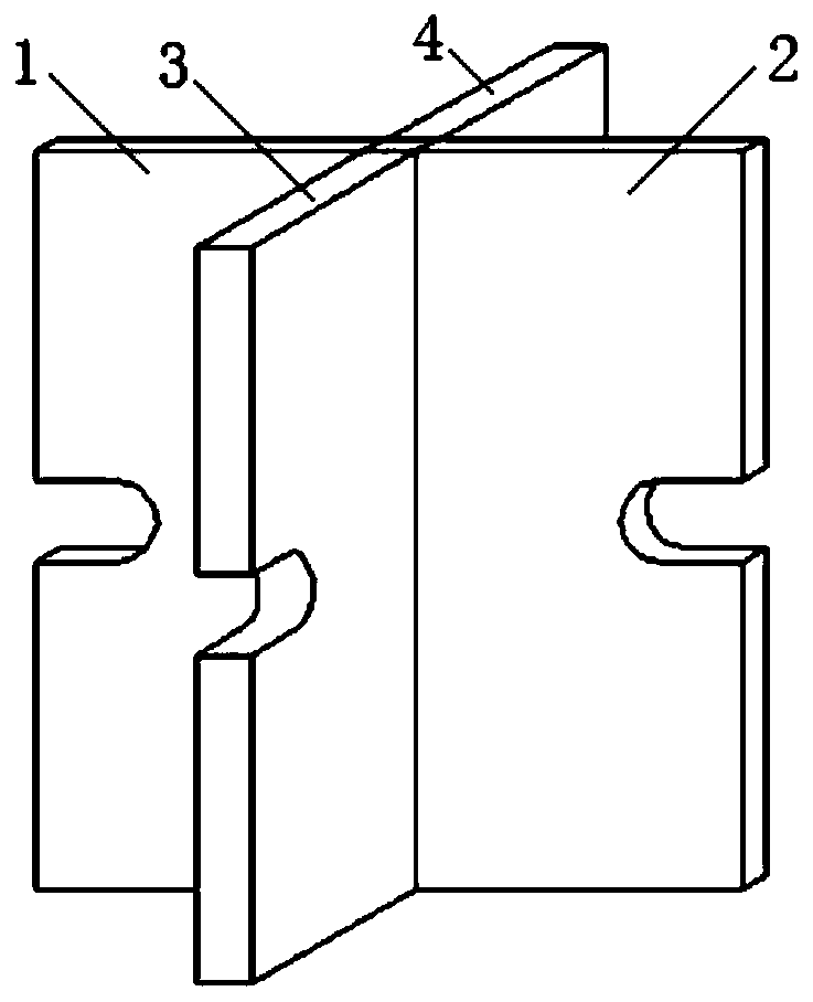
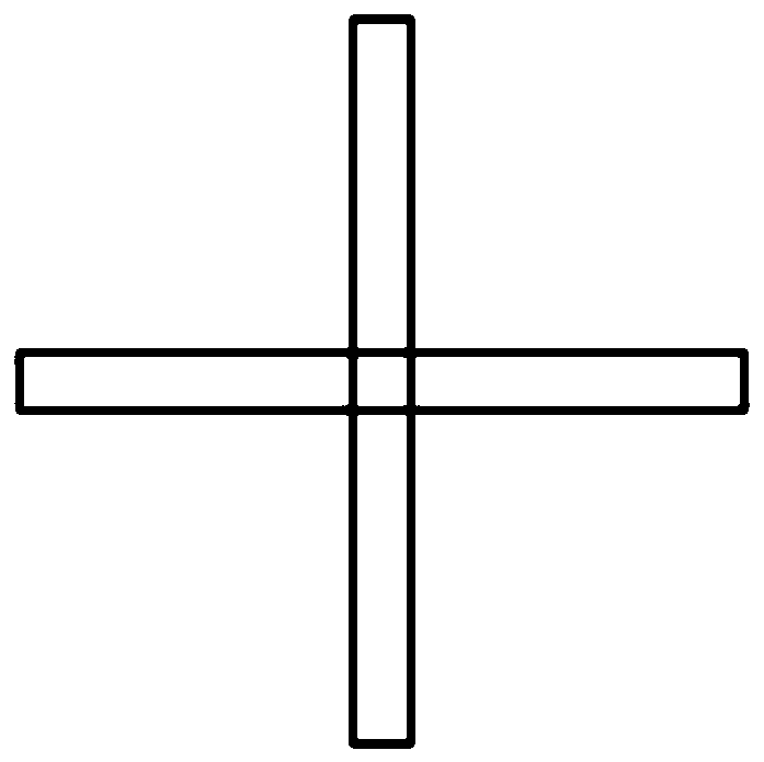
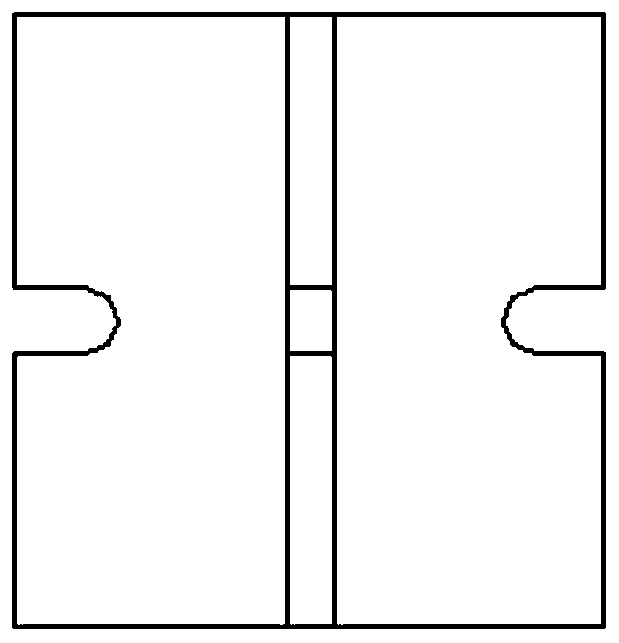
[0027] Such as Figures 1 to 3 As shown, the shear connector includes the first limb plate 1, the second limb plate 2, the third limb plate 3 and the fourth limb plate 4, and the third limb plate 3 and the fourth limb plate 4 are butt welded to form a vertical plate , the first limb plate 1 is vertically welded to the middle position of the left end face of the vertical plate, the second limb plate 2 is welded vertically to the middle position of the right end face of the vertical plate, the first limb plate 1 and the second limb plate 2 are aligned left and right, and from the top Looking down, the shear connector is in the shape of a cross; the first limb plate 1, the second limb plate 2, the third limb plate 3 and the fourth limb plate 4 have opening holes for inserting steel bars in the middle positions of the respective outer sides. The hole is "U" shaped. In this embodiment, the first limb board 1 , the second limb board 2 , the third limb board 3 and the fourth limb bo...

Embodiment 2

[0029] Such as Figures 4 to 6 As shown, the structure of the shear connector is basically the same as that of Embodiment 1, the difference is that the shear connector is welded by two angle steel limbs, and the four opening holes are correspondingly opened on the four sides of the two angle steel (limbs).

[0030] The method for using the shear connector for the corrugated steel web-concrete composite box girder bridge structure of the present invention is:

[0031] Such as Figure 7 As shown, the concrete roof and floor are set on the corrugated steel web, and multiple cross-shaped shear connectors are arranged on the concrete roof and floor in an array and fixed by welding. Horizontal and longitudinal steel bars alternately pass through the opening holes on the corresponding shear connectors. After the steel bars are arranged, multiple cross-shaped shear connectors and horizontal and longitudinal steel bars form a whole.


PUM


Abstract

The invention relates to a shear connecting piece for a corrugated steel web-concrete combined box girder bridge structure, and belongs to the field of bridge construction. In the shear connecting piece structure, a third limb plate and a fourth limb plate are welded to form a vertical plate, a first limb plate and a second limb plate are respectively and vertically welded to the middle positions of the left end face and the right end face of the vertical plate respectively, the first limb plate and the second limb plate are aligned left and right, the shear connection pieces are in a cross shape; the middle positions of the outer sides of the first limb plate, the second limb plate, the third limb plate and the fourth limb plate are respectively provided with an opening hole used for penetrating the steel bars. According to the cross-shaped shear connection piece structure, the transverse shear resistance is improved through the arrangement of the first and second limb plates, the longitudinal shearing resistance requirement is guaranteed by the third limb plate and the fourth limb plate, so that the shearing resistance and the applicability of the connecting part of the steel-concrete combined box girder bridge are met; in addition, the cross-shaped shear connector further has the advantages of being simple in structure, saving in materials, easy to weld and construct, small in welding amount and capable of saving manufacturing cost.

Description

technical field [0001] The invention belongs to the field of bridge construction and relates to a shear force connector for a corrugated steel web-concrete composite box girder bridge structure. Background technique [0002] In the bridge structure, the corrugated steel web-concrete composite box girder structure uses the corrugated steel plate as the web, and the steel web is connected with the concrete top and bottom plates. Collaboration between concrete elements. Therefore, in this steel-concrete composite structure, the shear connector is particularly important, which is directly related to the bearing capacity of the entire box girder structure. [0003] In the development process of shear connectors for box girder structures, in the early 1950s, spiral reinforcement and bending reinforcement connectors were mainly used, and later they were gradually replaced by stud connectors. In the 1980s, PBL connectors changed the dominant position of stud connectors. In recent ...

Claims


Application Information

Patent Timeline
Patent Type & Authority Applications(China)
IPC IPC(8): E01D19/12E01D2/04E01D101/26E01D101/30
CPCE01D2/04E01D19/125E01D2101/26E01D2101/30
Inventor 贾慧娟吴凯施博文陈曦张弦王倩
Owner JINLING INST OF TECH
Why Eureka
Try Eureka