
Multifunctional spliced floor and floor system constituted by same

A multi-functional board and splicing technology, which is applied to local raised floors, building structures, floors, etc., can solve problems such as unfavorable circuit and pipeline laying, cumbersome assembly, and easy to disperse, so as to improve the scope of use, Various splicing methods and stable structure

Pending Publication Date: 2019-09-20
FOSHAN LOKANG PLASTIC PROD CO LTD
View PDF0 Cites 0 Cited by
  • Summary
  • Abstract
  • Description
  • Claims
  • Application Information

AI Technical Summary

Problems solved by technology

Existing splicing sports floors are generally suitable for indoor or outdoor flat ground. Sports floors cannot be used in some more complex ground environments, such as sand, wetlands, grass, etc. As far as the current assembled sports floors are concerned, it is impossible to use sports floors. in use
However, the more complicated the ground environment is, the more it needs the sports floor to provide a dry, firm and flat ground environment, but there is no assembled sports floor that can be used in the harsh ground environment; the single assembled floor of the existing assembled sports floor is relatively small It is large and cumbersome to assemble, requiring special tools and operators to assemble. The assembled floor has no special locking structure, and it is easy to disperse when it is impacted by external forces. This also brings difficulties to the use of spliced ​​floors. In addition, the existing The splicing of the assembled sports floor is relatively rigid, and it is difficult to adjust according to the actual use environment. Its single function is not conducive to the laying of circuits and pipelines

Method used


Image

  • Multifunctional spliced floor and floor system constituted by same
  • Multifunctional spliced floor and floor system constituted by same
  • Multifunctional spliced floor and floor system constituted by same

Examples


Embodiment 1

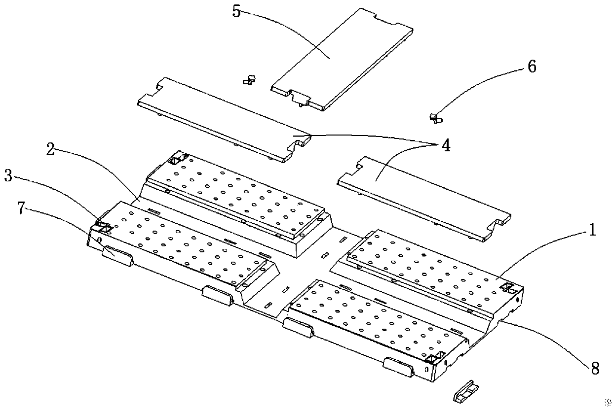
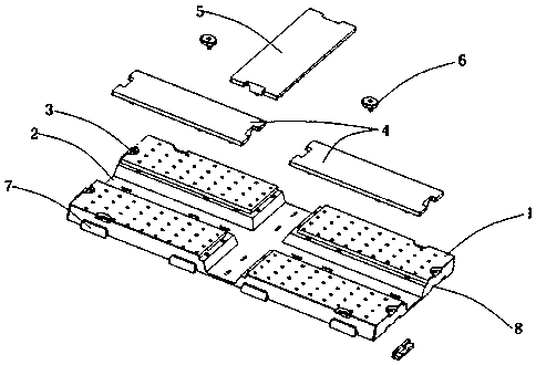
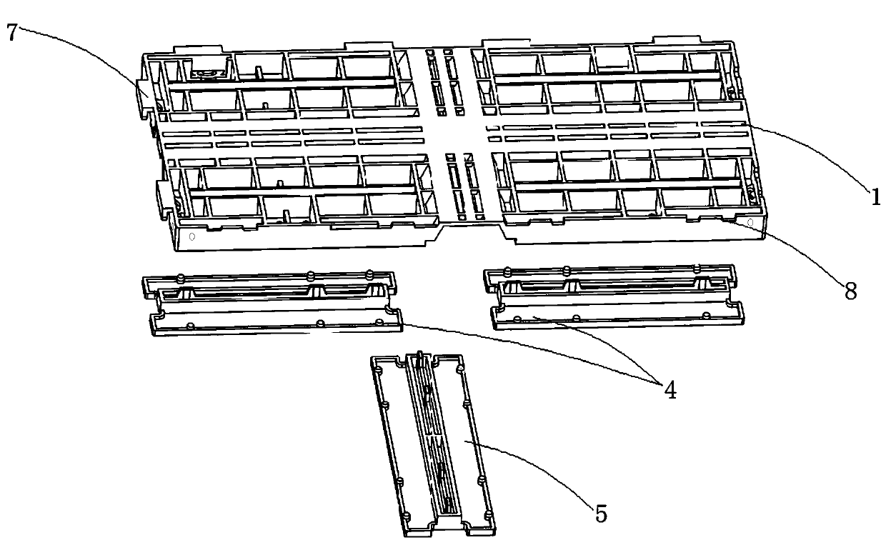
[0061] This embodiment provides a multi-functional mosaic floor, including at least one rectangular multi-functional board 1, the main structure of the multi-functional board 1 is as follows figure 1 , figure 2 , image 3 , Figure 4 , Figure 5 As shown, the middle part is provided with a cross-shaped recessed through groove 2, and the upper part of the through groove 2 is respectively covered with two detachable horizontal first cover plates 4 and a longitudinal second cover plate 5; the first cover After the plate 4 and the second cover plate 5 cover the through groove 2, the surface of the first cover plate 4, the surface of the second cover plate 5 and the upper surface of the multifunctional plate 1 can form a flat plane;

[0062] The four sides of the multi-function board 1 are also provided with outwardly extending tabs 7 and draw-in grooves 8 located at the lower part of the edge. Fitting movable connection with card slot 8;

[0063] Each edge of the upper part ...

Embodiment 2

[0068] This embodiment further defines the structure of the lock groove 3 on the basis of the above embodiments, such as figure 2 As shown, the lock groove 3 is divided into two parts, and each part is arranged on each edge of the upper part of the multi-function board 1. After the adjacent multi-function boards 1 are combined, the two parts of the lock groove 3 can be combined to form a complete Lock slot 3. Other parts of this embodiment are the same as those of the foregoing embodiment, and will not be repeated here.

Embodiment 3

[0070] On the basis of the above-mentioned embodiments, this embodiment further defines the structure of the locking key 6 and the locking groove 3, such as Figure 10 , Figure 11 As shown, the lock key 6 is mainly composed of a circular lock handle 61 and two lock cylinders 62 symmetrically fixed at the bottom of the lock handle 61, and the free ends of the lock cylinders 62 are provided with columns with a diameter larger than that of the lock cylinder 62. A shape lock block 63, the center of the upper surface of the lock handle 61 is provided with a blind hole 64 in a hexagonal column; the lock groove 3 is a circular groove a31 structure composed of two semicircular grooves a31, each half The bottom of the circular groove body a31 is provided with an arc-shaped chute b32, and one end of the chute b32 is provided with a lock hole c33 whose diameter is greater than the width of the chute b32; the width of the chute b32 is not less than the diameter of the lock post 62, And ...


PUM


Abstract

The invention discloses a multifunctional spliced floor. The multifunctional spliced floor comprises one or more rectangular multifunctional plates, cross-shaped sunken through grooves are formed in the middles of the multifunctional plates, and the upper part of each through groove is covered with two separable transverse first cover plates and a longitudinal second cover plate; clamping tongues extending outwards and clamping grooves located in the lower parts of the edges are further formed in the four edges of each multifunctional plate; and one or more locking grooves are further formed in each edge of the upper parts of the multifunctional plates, locking keys are inserted into the locking grooves to lock the adjacent multifunctional plates, and the length of the short edges of the multifunctional plates is half of the length of the long edges of the multifunctional plates. The invention further discloses a floor system, and the floor system is mainly constituted by the multifunctional spliced floors in a transversely and longitudinally spliced mode. By additionally forming the through grooves, and wire arrangement inside the floor is realized; by additionally arranging locking structures, the locking process is conducted after floor splicing, and locking is more convenient and rapider; and the structure is simple, assembling is convenient, the splicing mode is diverse, the multifunctional spliced floor can adapt to the complex mounting environment, and the using range is expanded.

Description

technical field [0001] The invention relates to the field of floor technology, in particular to a multifunctional spliced ​​floor and a floor system formed therefrom. Background technique [0002] Traditional floors are generally made of wood. With the diversification of needs, the types of floors are also becoming more and more abundant. For example, with the rapid increase in the needs of cultural and sports activities, various venues have been widely established, and sports floors have become increasingly important. The types of manufacturing materials for sports floors have increased, including wood boards, composite boards, and polymer composite (plastic) boards. [0003] At present, most sports floors adopt an assembled structure, which is convenient for temporary handling and assembly. Existing splicing sports floors are generally suitable for indoor or outdoor flat ground. Sports floors cannot be used in some more complex ground environments, such as sand, wetlands...

Claims


Application Information

Patent Timeline
Patent Type & Authority Applications(China)
IPC IPC(8): E04F15/02E04F15/024E04F15/10
CPCE04F15/02038E04F15/02405E04F15/105E04F15/02172E04F2201/0523E04F2201/0558
Inventor 余德辉
Owner FOSHAN LOKANG PLASTIC PROD CO LTD
Learn More