Multi-unmanned aerial vehicle cooperative positioning method based on time delay compensation

A time-delay compensation and collaborative positioning technology, applied in positioning, radio wave measurement systems, instruments, etc., can solve the problems that the accuracy of time delay estimation cannot break through the sampling interval, unfavorable engineering implementation, and restrictions on passive time difference positioning performance, etc., to achieve reduction Small UAV load, precise positioning performance, and the effect of reducing requirements

Active Publication Date: 2019-09-20
NANJING UNIV OF AERONAUTICS & ASTRONAUTICS
View PDF7 Cites 9 Cited by
  • Summary
  • Abstract
  • Description
  • Claims
  • Application Information

AI Technical Summary

Problems solved by technology

However, in actual engineering, all digital signals are processed. Due to the limitation of sampling frequency, the accuracy of time delay estimation cannot break through the sampling interval, which greatly restricts the performance of passive time difference positioning
The existing solutions include fitting or interpolation, but the increase in the amount of data puts forward higher requirements on the hardware, which is not conducive to engineering implementation, especially on limited load platforms such as drones

Method used


Image

  • Multi-unmanned aerial vehicle cooperative positioning method based on time delay compensation
  • Multi-unmanned aerial vehicle cooperative positioning method based on time delay compensation
  • Multi-unmanned aerial vehicle cooperative positioning method based on time delay compensation

Examples


Embodiment Construction

[0033] The technical solutions of the present invention will be further described below in conjunction with the accompanying drawings and embodiments.

[0034] Symbol representation: symbol (.) in the present invention * means conjugation, Indicates a rounding operation.

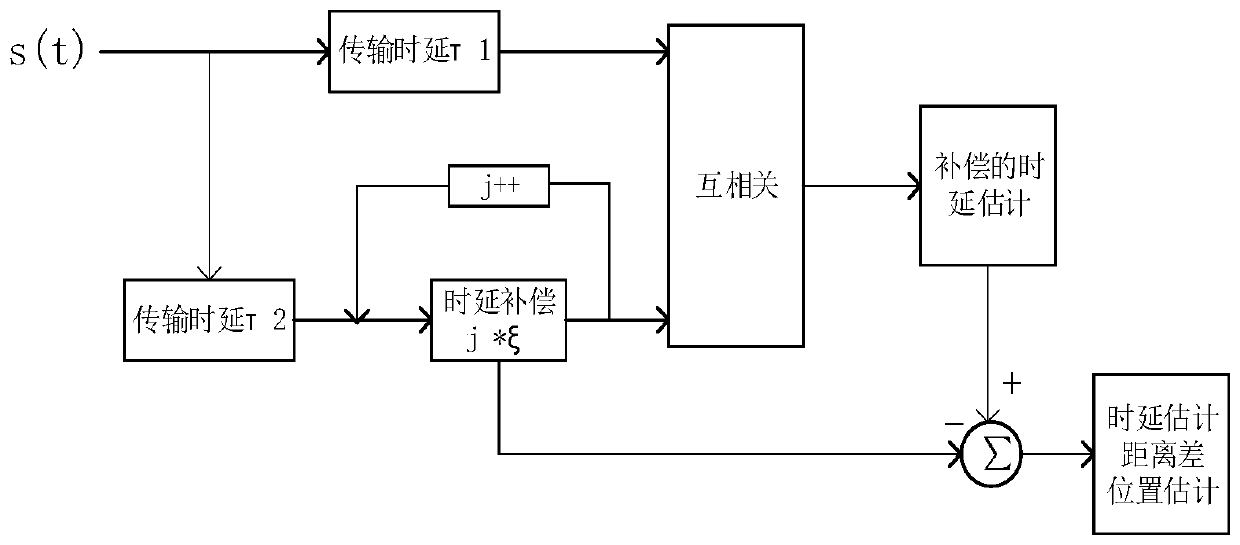
[0035] The multi-UAV cooperative positioning method based on delay compensation described in the present invention, the detailed process is as follows figure 1 shown. This method is used in a distributed passive positioning system composed of multiple UAVs to locate fixed radiation sources. Each UAV transmits the sampled received signal to the control center for centralized processing, and the control center outputs the final positioning result. The UAV synchronously receives the radiation source signal and performs sampling processing; selects the reference signal, performs delay compensation on the remaining signals, and performs cross-correlation processing with the reference signal; based on the opt...


PUM


Abstract

The invention discloses a multi-unmanned aerial vehicle cooperative positioning method based on time delay compensation, which is applied to a distributed passive positioning system consisting of a plurality of unmanned aerial vehicles. The multi-unmanned aerial vehicle cooperative positioning method concretely comprises the steps that: an unmanned aerial vehicle synchronously receives radiation source signals and samples the received signals; a reference signal is selected to perform time delay compensation on the rest signals, and the rest signals and the reference signals are subjected to cross-correlation processing; based on an optimal cross-correlation result, a time delay value and a corresponding compensation value are determined, and a high-precision time delay estimation is obtained through combination; according to the time delay estimation, a distance difference between the radiation source and each unmanned aerial vehicle, and a hyperbolic equation set is established to solve the position of the radiation source. The multi-unmanned aerial vehicle cooperative positioning method breaks through the fence limited by sampling precision in the prior art, and can obtain accurate time delay estimation superior to the sampling interval, thereby effectively improving the positioning precision; according to the method, high-resolution estimation can be obtained without relying on a high sampling rate, and the requirement on A / D equipment is reduced, so that the load of the unmanned aerial vehicle is effectively reduced, and the method has important application value.

Description

technical field [0001] The present invention relates to a passive positioning method, in particular to a multi-UAV cooperative positioning method based on delay compensation. Background technique [0002] The passive positioning system has a wide range of application platforms. Among them, the ground-based platform based on the ground radar system is easy to implement because the observation station is fixed, but it is greatly affected by the complex environment on the ground and has poor flexibility. The UAV-based space-based platform is not affected by the complex environment on the ground, has a wide range of observations, and has strong flexibility. It has incomparable advantages over land-based platforms, but it also brings new challenges to engineering implementation and load. [0003] Passive time difference positioning is a positioning technology that determines the distance difference between the target and the observation station based on the electromagnetic signal...

Claims


Application Information

Patent Timeline
Patent Type & Authority Applications(China)
IPC IPC(8): G01S5/06
CPCG01S5/06
Inventor 李建峰何益张小飞
Owner NANJING UNIV OF AERONAUTICS & ASTRONAUTICS
Why Eureka
Try Eureka