
Positioning mechanism, optical remote sensor and spatial reflector positioning method

A positioning mechanism and mirror technology, applied in optics, optical components, instruments, etc., can solve problems such as affecting the surface of the mirror, drilling and reaming producing a large impact force, and deviating from the original position of the mirror.

Inactive Publication Date: 2019-09-20
CHANGCHUN INST OF OPTICS FINE MECHANICS & PHYSICS CHINESE ACAD OF SCI
View PDF7 Cites 1 Cited by
  • Summary
  • Abstract
  • Description
  • Claims
  • Application Information

AI Technical Summary

Problems solved by technology

The problems caused by this positioning method are: 1. During the matching process, drilling and reaming will generate a large impact force, which will deviate the mirror from its original position, especially for the structural rigidity of the bearing mirror. 2. The shear force in the matching process will generate local stress, and such stress will remain in the structure. In the subsequent test and test process, it may be transmitted to the vicinity of the installation point of the reflector from Does not affect the surface shape of the mirror

Method used


Image

  • Positioning mechanism, optical remote sensor and spatial reflector positioning method
  • Positioning mechanism, optical remote sensor and spatial reflector positioning method

Examples


Embodiment Construction

[0024] The following will clearly and completely describe the technical solutions in the embodiments of the present invention with reference to the accompanying drawings in the embodiments of the present invention. Obviously, the described embodiments are only some, not all, embodiments of the present invention. Based on the embodiments of the present invention, all other embodiments obtained by persons of ordinary skill in the art without making creative efforts belong to the protection scope of the present invention.

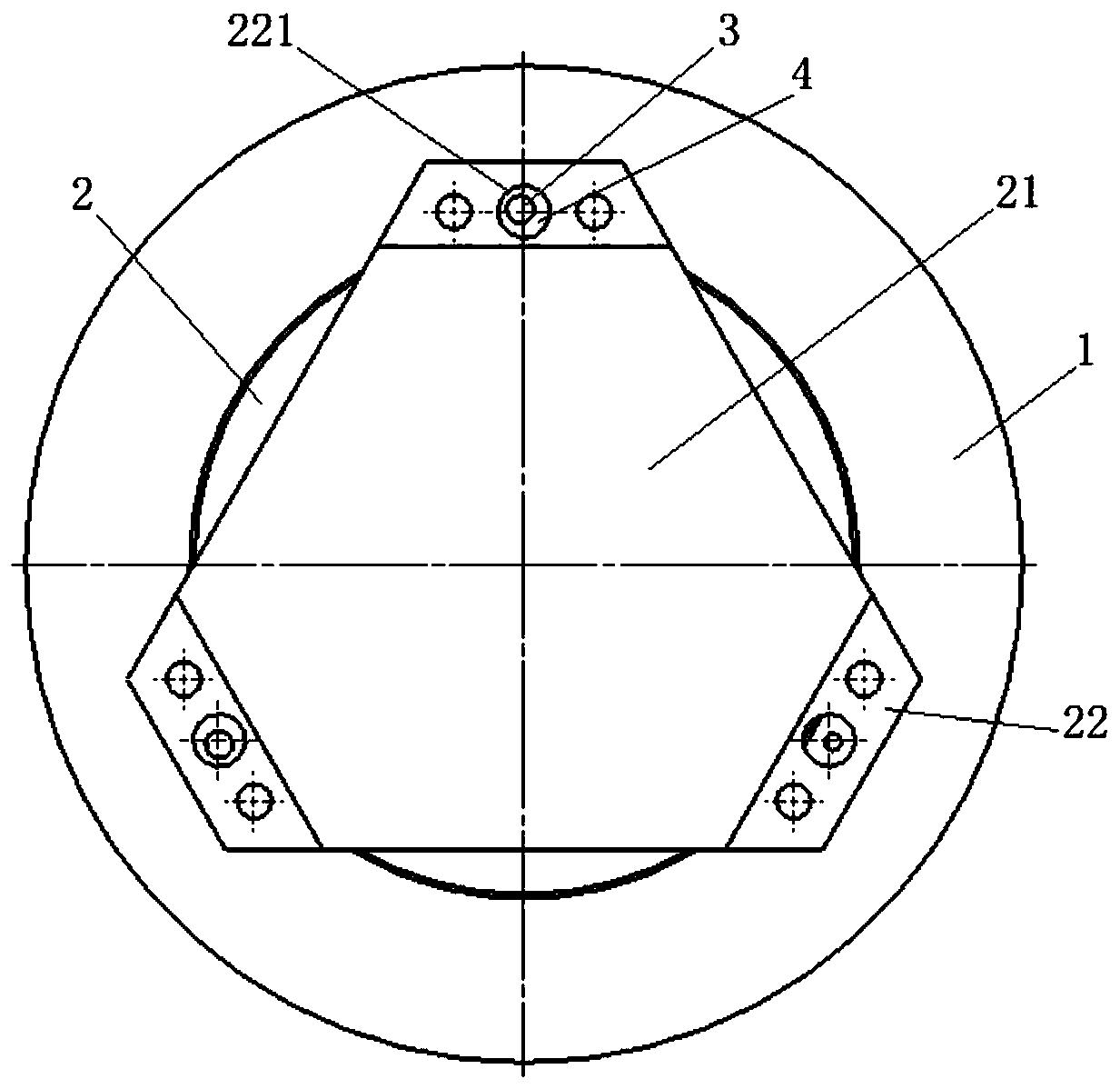
[0025] see figure 1 as well as figure 2 , an embodiment of the present invention provides a positioning mechanism, including a first component and a second component, the second component is installed on the first component, and the positioning mechanism is used to realize precise positioning between the first component and the second component, specifically Ground, a first pin hole 11 is opened on the first component, a second pin hole 221 is opened on the ...


PUM


Abstract

The invention provides a positioning mechanism. The positioning mechanism comprises a first assembly and a second assembly; the second assembly is arranged on the first assembly; a first pin hole is formed in the first assembly; a second pin hole corresponding to the first pin hole is formed in the second assembly; an eccentric pin sleeve is screwed in the second pin hole; an eccentric pin is positioned in the first pin hole; and the eccentric pin is partially sleeved with the inner hole of the eccentric pin sleeve. The invention further provides an optical remote sensor. The optical remote sensor comprises the positioning mechanism. The invention further provides a spatial reflector positioning method. According to the positioning mechanism of the invention, the precise positioning of two components can be realized through the eccentric pin and the eccentric pin sleeve; and a matched punching link does not exist in an assembling process, so that no change and no stress are generated for the structure. When being applied to the spatial remote sensor, the positioning mechanism can realize precise positioning without affecting the position and surface shape of a reflector.

Description

technical field [0001] The invention belongs to a space optical remote sensor, in particular to a positioning mechanism, an optical remote sensor and a space mirror positioning method. Background technique [0002] For space optical remote sensors, the degree of deviation between the position and surface shape of the mirror and the theoretical value determines the availability of the optical system, and the position tolerance of some optical systems for the mirror is even accurate to the micron level, so in the assembly process, Strict control of assembly stress is very important. [0003] At present, the conventional positioning method of the reflector of the optical remote sensor is that the installer adjusts the position of the reflector through the measuring instrument, and then positions the reflector with a column pin or a vertical pin. The problems caused by this positioning method are: 1. During the matching process, drilling and reaming will generate a large impact...

Claims


Application Information

Patent Timeline
Patent Type & Authority Applications(China)
IPC IPC(8): G02B7/182
CPCG02B7/182G02B7/1822G02B7/1821
Inventor 刘晓丰程志峰
Owner CHANGCHUN INST OF OPTICS FINE MECHANICS & PHYSICS CHINESE ACAD OF SCI
Learn More