Transmission line

A transmission line and signal line technology, applied in the field of signal transmission, can solve the problems of signal loss mutation and leakage of plane transmission line, and achieve the effect of reducing mutation mutation, improving reliability, and reducing signal leakage.

Active Publication Date: 2019-09-20
AAC PRECISE MFG TECH CHANGZHOU
View PDF7 Cites 1 Cited by
  • Summary
  • Abstract
  • Description
  • Claims
  • Application Information

AI Technical Summary

Problems solved by technology

However, the existing planar transmission lines generally have the problems of sudden change in loss and signal leakage.

Method used


Image

  • Transmission line
  • Transmission line
  • Transmission line

Examples


Embodiment Construction

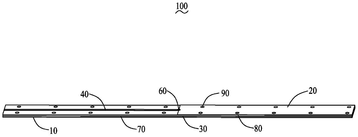
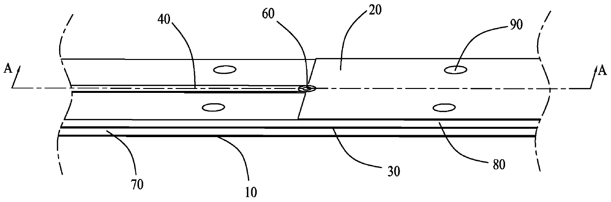
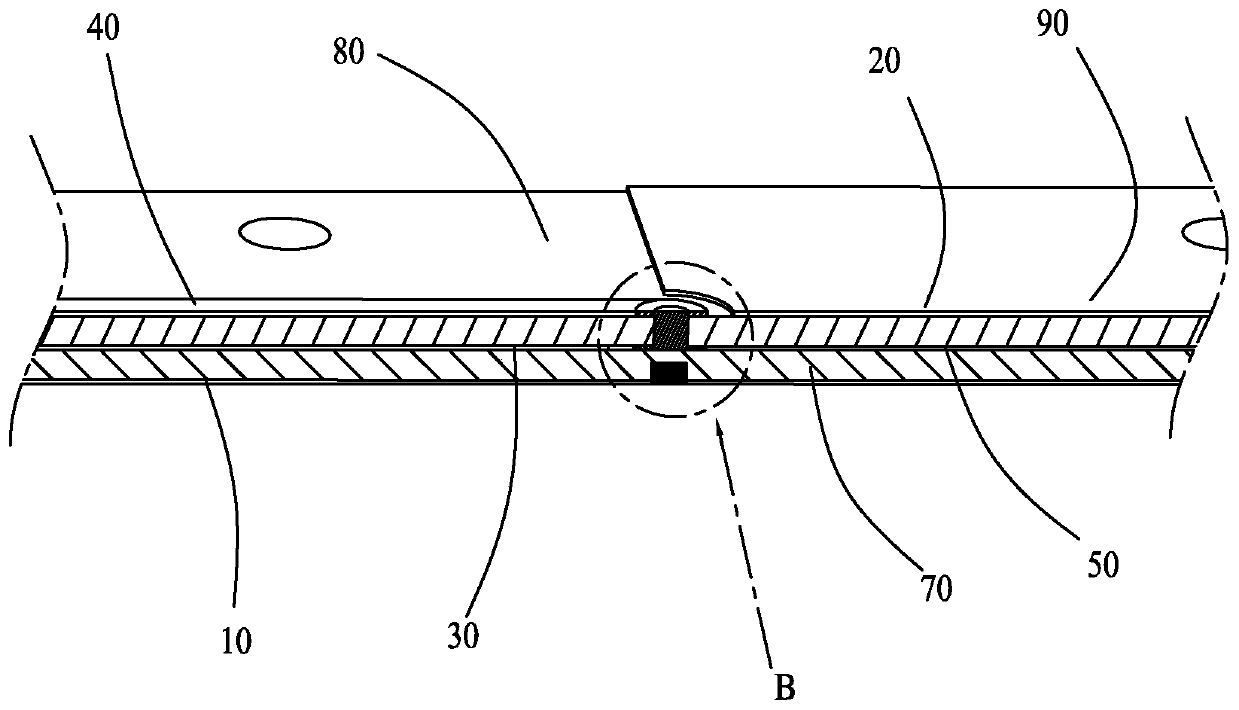
[0031] Attached below Figure 1-11 and embodiments to further illustrate the present invention.

[0032] It should be noted that all directional indications (such as up, down, left, right, front, back, inside, outside, top, bottom...) in the embodiments of the present invention are only used to explain As shown in the figure), if the relative positional relationship between the various components, etc., if the specific posture changes, the directional indication will also change accordingly.

[0033] It should also be noted that when an element is referred to as being “fixed” or “disposed on” another element, the element may be directly on the other element or there may be an intervening element at the same time. When an element is referred to as being "connected to" another element, it can be directly connected to the other element or intervening elements may also be present.

[0034] see figure 1 , figure 2 and image 3 , according to an embodiment of the present inven...


PUM


Abstract

The invention provides a transmission line, which includes a first grounding layer, a second grounding layer spaced apart from the first grounding layer, and a third grounding layer located between the first grounding layer and the second grounding layer. The transmission line is characterized in that the transmission line also includes a micro-strip line signal line for transmitting signals, a conductive blind hole electrically connected with the micro-strip line signal line, and a strip-line signal line electrically connected with the micro-strip line signal line through the conductive blind hole; the third grounding layer is provided with an avoidance slot, and the strip-line signal line is located in the avoidance slot; the micro-strip line signal line is located on one side of the third grounding layer away from the first grounding layer; the conductive blind hole is located between the second grounding layer and the third grounding layer, and one end of the conductive blind hole extends into the avoidance slot; and the first grounding layer is provided with a tuning blind hole which extends towards the conductive blind hole, and a parasitic capacitor is formed between the tuning blind hole and the conductive blind hole. By setting the tuning blind hole, the problems of differential loss mutation and signal leakage at the conductive blind hole can be reduced.

Description

[0001] 【Technical field】 [0002] The invention relates to the field of signal transmission, in particular to a transmission line. [0003] 【Background technique】 [0004] The layout of existing coaxial transmission lines requires a certain amount of space, which has certain limitations in the interior of rapidly developing terminal products. Due to the characteristics of low profile, planar transmission lines are more and more widely used in terminal products. However, the existing planar transmission lines generally have the problems of sudden change in loss and signal leakage. [0005] Therefore, it is necessary to provide a transmission line that improves the above problems. [0006] 【Content of invention】 [0007] The object of the present invention is to provide a transmission line that reduces the problems of sudden loss and signal leakage. [0008] To achieve the above object, the present invention provides a transmission line, comprising a first ground layer, a seco...

Claims


Application Information

Patent Timeline
IPC IPC(8): H01P3/18
CPCH01P3/18
Inventor 陈勇利王建安许心影
Owner AAC PRECISE MFG TECH CHANGZHOU
Why Eureka
Try Eureka