
Waveguide filter with welding structure

A waveguide filter and welding structure technology, which is applied to waveguide devices, electrical components, circuits, etc., can solve the problems of surface flatness, tolerance difference of finish, high cost and scrap rate, poor contact between cavity and cover plate, etc. , to achieve good consistency, reduce signal leakage, and simple structure

Inactive Publication Date: 2013-01-16
KAELUS COMM EQUIP SHANGHAI
View PDF2 Cites 1 Cited by
  • Summary
  • Abstract
  • Description
  • Claims
  • Application Information

AI Technical Summary

Problems solved by technology

Due to the difference in surface flatness and finish tolerance of these parts during the processing process, the cavity and the cover plate are poorly contacted during the assembly process, resulting in a large number of signal leaks
In order to solve this problem, it is necessary to improve the precision of machining or increase the fixing screws, so that the cost and scrap rate will become higher

Method used


Image

  • Waveguide filter with welding structure

Examples


Embodiment

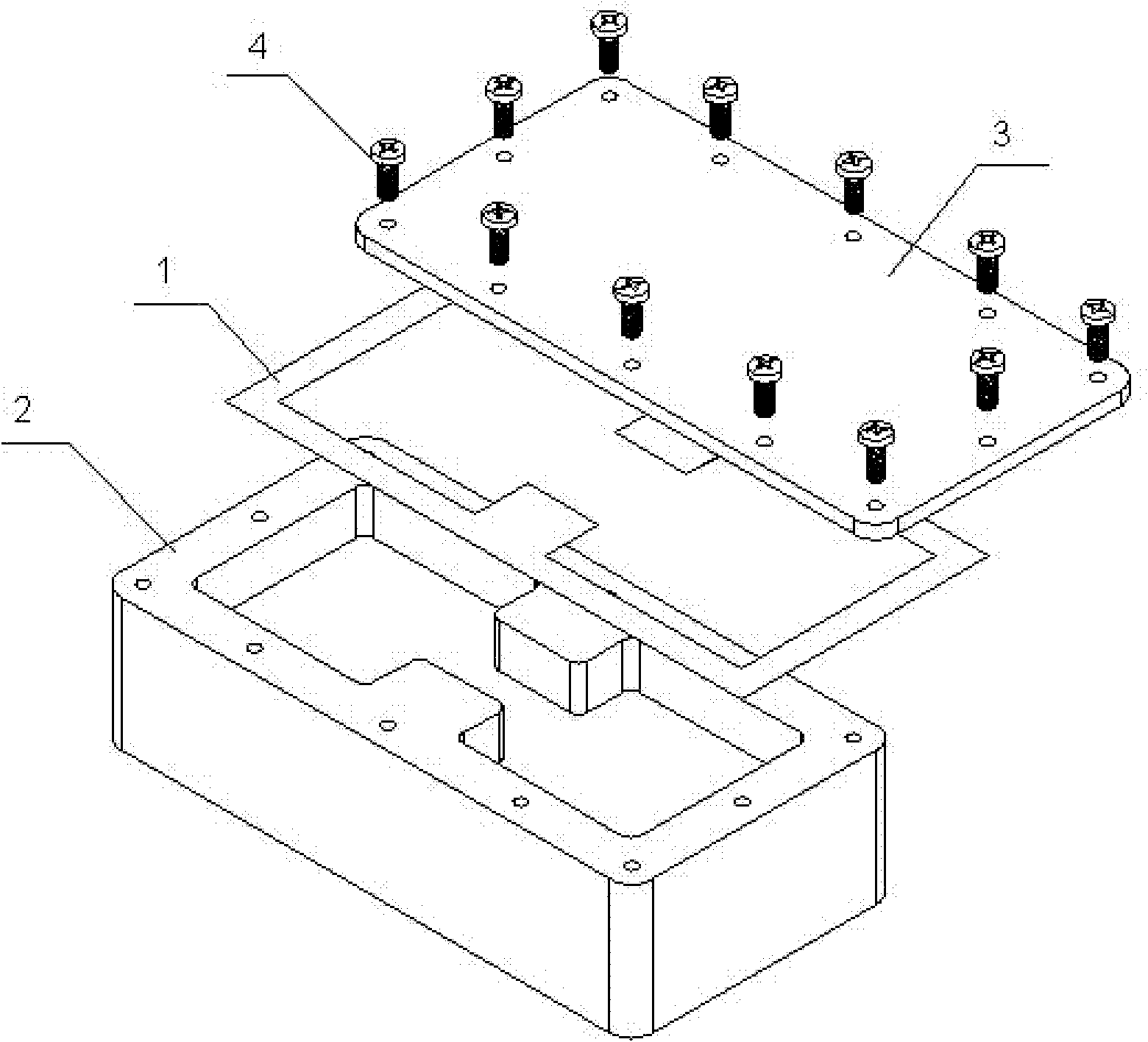
[0020] Such as figure 1 As shown, a waveguide filter with a welded structure, the cover plate 3 is set above the cavity 2, and a layer of solder layer 1 with the same shape as the upper surface of the cavity 2 is provided between the two, and the fastening screw 4 passes through The solder layer 1 fixes the cover plate 3 and the cavity 2 so that they are closely connected. The solder layer 1 is a solder paste composed of flux and solder powder and soldered by reflow welding, so that the cavity 2 and the cover plate 3 are in close contact, and the number of fastening screws 4 can also be reduced. This welding structure can effectively reduce signal leakage even if the processing precision of the cover plate and the cavity is not high, so that the product performance is reliable and the cost is reduced.


PUM


Abstract

The invention relates to a waveguide filter with a welding structure. The waveguide filter comprises a cavity and a cover plate, wherein the cover plate is arranged above the cavity; and the waveguide filter is characterized by also comprising a tin soldering layer, wherein the tin soldering layer is arranged between the cover plate and the cavity; and the shape of the tin soldering layer is the same as that of the upper surface of the cavity. Compared with the prior art, the waveguide filter has the advantages of effectively reducing the signal leakage, along with simple structure, reliable performance, low cost and the like.

Description

technical field [0001] The invention relates to a waveguide filter, in particular to a waveguide filter with a welded structure. Background technique [0002] The waveguide filter has the function of frequency selection, which can separate the frequency, that is, pass the signal of the required frequency and suppress the signal of the unnecessary frequency, which is one of the core designs in radio technology. [0003] The cavity waveguide filter frequency covers 0.5-50GHz. Due to the high Q value structure design, the filter has the ability to work at high power, has low insertion loss, good passband standing wave and high out-of-band Attenuation, good temperature stability, especially suitable for narrowband applications, widely used in radar, electronic countermeasures series products, microwave communication, radio frequency simulation and other fields. [0004] With the rapid development of wireless communication systems, the use of frequencies is getting higher and hi...

Claims


Application Information

Patent Timeline
IPC IPC(8): H01P1/207
Inventor 程晓辉
Owner KAELUS COMM EQUIP SHANGHAI
Learn More