Modified detection coil

A detection coil and frame technology, applied in the field of improved detection coils, can solve the problems of long time for tuning and matching, influence of signal shielding effect, complex assembly and assembly, etc., to reduce signal leakage, improve shielding effect, and improve production efficiency Effect

Pending Publication Date: 2017-03-15
SUZHOU NIUMAG ELECTRONICS TECH
View PDF10 Cites 0 Cited by
  • Summary
  • Abstract
  • Description
  • Claims
  • Application Information

AI Technical Summary

Problems solved by technology

[0002] At present, the structure of the detection coil used to detect signals is usually assembled and connected by four aluminum blocks. On the one hand, the process is relatively cumbersome, and on the other hand, the assembly and assembly are relatively complicated. Secondly, the signal shielding effect is slightly affected due to the connection of multiple screws. , since the assembly screws are made of 304 stainless steel, there will be a small impact on the magnetic field
[0003] In addition, the existing probe coil structure has a slight impact on the resonance point during the tuning and matching process, and the tuning and matching takes a long time. To solve this problem, the processing technology of the probe coil has been improved.

Method used


Image

  • Modified detection coil
  • Modified detection coil
  • Modified detection coil

Examples


Embodiment Construction

[0034] The above solution will be further described below in conjunction with specific embodiments. It should be understood that these examples are used to illustrate the present invention and not to limit the scope of the present invention. The implementation conditions used in the examples can be further adjusted according to the conditions of specific manufacturers, and the implementation conditions not indicated are usually the conditions in routine experiments.

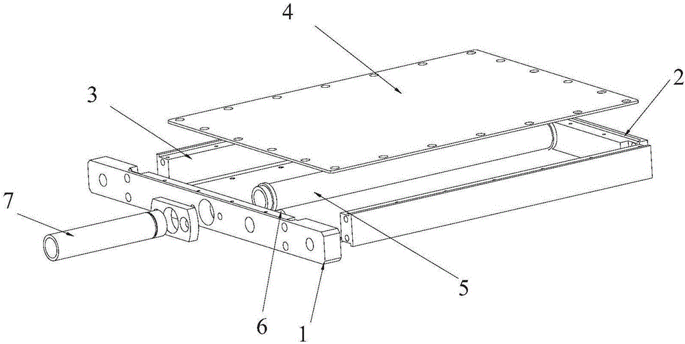
[0035] see figure 1 , is a structural schematic diagram of the detection coil in the prior art, which includes a detection coil front plate 1, a detection coil rear plate 2, two detection coil side plates 3, a detection coil shielding plate 4, a detection coil skeleton 5, an adjustable capacitor 6 and The detection coil waveguide 7, the detection coil front plate 1, the detection coil rear plate 2 and the two detection coil side plates 3 are sequentially connected to form a receiving groove, one end of the adjus...


PUM


Abstract

The invention discloses a modified detection coil, comprising an integration structured detection coil frame (9), detection coil shielding plates (10) arranged at two sides in the width of the detection coil frame (9), and a detection coil wave guiding tube (13). The detection coil frame (9) is provided therein with a containing cavity. The containing cavity is provided therein with an adjustable capacitor (12) and a detection coil framework (11). One end of the adjustable capacitor (12) is fixedly arranged on the front end plate (9-3) of the detection coil frame (9) and the other end extends towards the containing cavity. One end of the detection coil framework (11) is fixedly arranged on the back end plate (9-4) of the detection coil frame (9) and the other end extends towards the containing cavity. One end of the detection coil wave guiding tube (13) is fixedly arranged on the front end plate (9-3) and the other end extends to the exterior part of the detection coil frame (9). The detection coil provided by the invention is simple in structure and can achieve an improved shielding effect.

Description

technical field [0001] The present invention relates to an improved search coil. Background technique [0002] At present, the structure of the detection coil used to detect signals is usually assembled and connected by four aluminum blocks. On the one hand, the process is relatively cumbersome, and on the other hand, the assembly and assembly are relatively complicated. Secondly, the signal shielding effect is slightly affected due to the connection of multiple screws. , Since the assembly screws are made of 304 stainless steel, there will be a small impact on the magnetic field. [0003] In addition, the existing probe coil structure has a slight impact on the resonance point during the tuning and matching process, and the tuning and matching takes a long time. To solve this problem, the processing technology of the probe coil has been improved. The present invention thus comes. Contents of the invention [0004] Based on the above problems, the purpose of the present ...

Claims


Application Information

Patent Timeline
Patent Type & Authority Applications(China)
IPC IPC(8): G01R31/00
CPCG01R31/00
Inventor 邹平松黄钢孙宝刚黄琳宋海伦
Owner SUZHOU NIUMAG ELECTRONICS TECH
Why Eureka
Try Eureka