Rotary cylinder clamping device for processing filter bases

A technology of rotating cylinder and clamping device, which is applied in the direction of clamping device, positioning device, metal processing equipment, etc.

Pending Publication Date: 2019-09-24
NINGBO JINDA AUTOMOBILE COMPONENTS
View PDF0 Cites 0 Cited by
  • Summary
  • Abstract
  • Description
  • Claims
  • Application Information

AI Technical Summary

Problems solved by technology

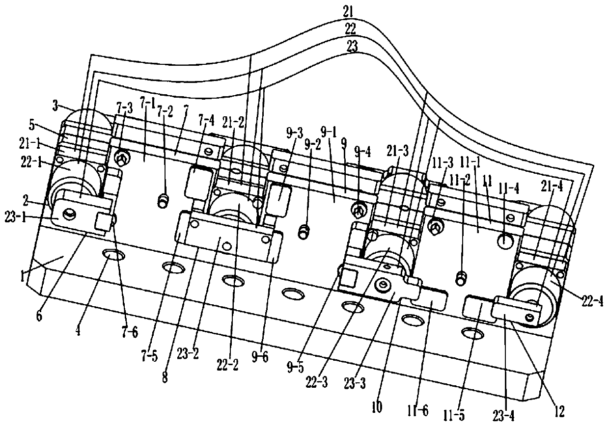
[0005] A rotary cylinder clamping device for processing filter bases, comprising a base plate, a first clamping assembly, a second clamping assembly and two fixing holes, the fixing holes are evenly distributed on the base plate, the The bottom plate is fixedly connected with the second clamping assembly and the first clamping assembly respectively, and the first clamping assembly includes a first connecting plate, a first air cylinder assembly, a first product fixing assembly, a second air cylinder assembly, a second product A fixing assembly, a third cylinder assembly, a third product fixing assembly and a fourth cylinder assembly, the fourth cylinder assembly, the third product fixing assembly, the third cylinder assembly, the second product fixing assembly, the second cylinder assembly, the first The product fixing assembly and the first cylinder assembly are sequentially fixed on the front side of the first connecting plate from 
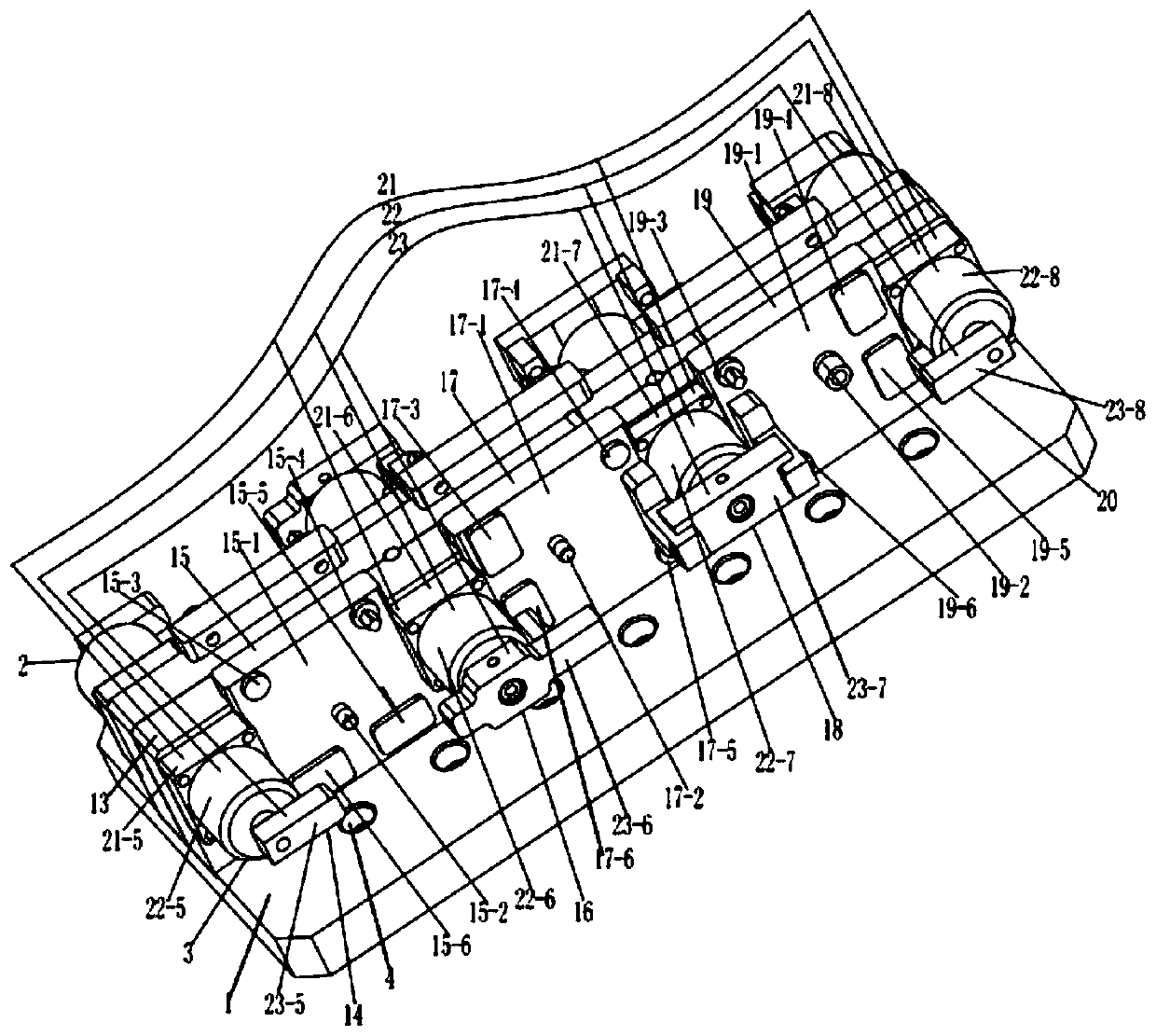
right to left, the first clamping assembly is located on the front side of the second clamping assembly, and the second clamping assembly includes a second connection plate, the fifth cylinder assembly, the fourth product fixing assembly, the sixth cylinder assembly, the fifth product fixing assembly, the seventh cylinder assembly, the sixth product fixing assembly and the eighth cylinder assembly, the eighth cylinder assembly, the sixth product The fixing assembly, the seventh cylinder assembly, the fifth product fixing assembly, the sixth cylinder assembly, the fourth product fixing assembly and the fifth cylinder assembly are fixed on the rear side of the second connecting plate from right to left, and the front side of the second connecting plate is located at The rear side of the first connecting plate, the first connecting plate and the second connecting plate are fixed on the bottom plate, because the fourth cylinder assembly, the third product fixing assembly, the third cylinder assembly, the second product The fixing assembly, the second cylinder assembly, the first product fixing assembly and the first cylinder assembly are fixed on the front side of the first connecting plate in turn from right to left, and the eighth cylinder assembly, the sixth product fixing assembly, the seventh cylinder assembly, the fifth The product fixing assembly, the sixth cylinder assembly, the fourth product fixing assembly and the fifth cylinder assembly are fixed on the rear side of the second connecting plate from right to left, so that the operator can put the 6 filter bases to be processed into the first In the first product fixing component, the second product fixing component and the third product fixing component on a connecting plate and in the fourth product fixing component, the fifth product fixing component and the sixth product fixing component on the second connecting plate, and then Clamp the 6 filter bases with the first cylinder assembly, the second cylinder assembly, the third cylinder assembly, the fourth cylinder assembly, the fifth cylinder assembly, the sixth cylinder assembly, the seventh cylinder assembly and the eighth cylinder assembly , so as to solve the traditional need for three different clamping devices to clamp the three sides of the filter base, and after each side is clamped, an external machine tool is used to process the side of the filter base, so that it is impossible to achieve a On the set of fixtures, multiple products are clamped at the same time, which leads to the problem of reduced work efficiency, so it has the characteristics of high work efficiency

Method used


Image

  • Rotary cylinder clamping device for processing filter bases
  • Rotary cylinder clamping device for processing filter bases

Examples


Embodiment Construction

[0019] The specific implementation manners of the present invention will be further described below in conjunction with the accompanying drawings, so as to make the technical solution of the present invention easier to understand and grasp.

[0020] Such as Figure 1 to Figure 2 As shown, a rotary cylinder clamping device for processing filter bases includes a bottom plate 1, a first clamping assembly 2, a second clamping assembly 3 and two and fixing holes 4, and the fixing holes 4 are uniform Distributed on the bottom plate 1, the bottom plate 1 is fixedly connected with the second clamping assembly 3 and the first clamping assembly 2 respectively, and the first clamping assembly 2 includes a first connecting plate 5, a first cylinder assembly 6 , the first product fixing assembly 7, the second cylinder assembly 8, the second product fixing assembly 9, the third cylinder assembly 10, the third product fixing assembly 11 and the fourth cylinder assembly 12, the fourth cylinde...


PUM


Abstract

The invention discloses the field of rotary cylinder clamping devices, and particularly discloses a rotary cylinder clamping device for processing filter bases. The rotary cylinder clamping device for processing the filter bases comprises a base plate, a first clamping assembly, a second clamping assembly and two fixing holes, wherein the first clamping assembly comprises a first connecting plate, a first cylinder assembly, a first product fixing assembly, a second cylinder assembly, a second product fixing assembly, a third cylinder assembly, a third product fixing assembly and a fourth cylinder assembly; and the second clamping assembly comprises a second connecting plate, a fifth air cylinder assembly, a fourth product fixing assembly, a sixth air cylinder assembly, a fifth product fixing assembly, a seventh air cylinder assembly, a sixth product fixing assembly and an eighth air cylinder assembly. An operator puts fix filter bases needing machining into the first clamping assembly and the second clamping assembly to be clamped, and the problem that in the prior art, a plurality of products cannot be clamped on one set of clamp at a time at the same time, and consequently the working efficiency is reduced is solved.

Description

technical field [0001] The invention discloses the field of rotary cylinder clamping devices, and more specifically discloses a rotary cylinder clamping device for processing filter bases. Background technique [0002] It affects the production efficiency, and the effect of clamping affects the quality. At present, the common quick clamps on the market are mainly manual operation. For the filter base with high product quality, due to the limited length of the manpower, the operator needs to walk around the product to be able to operate. If it is in place, it is easy to cause the clamping device and the filter base to fail to clamp, which affects the stability of the filter base during processing, which in turn leads to a high product scrap rate, and there are many traditional clamping devices, but all It is necessary to manually control the clamping and releasing of the filter bases of multiple products one by one in sequence, and the threaded hole pairs on the three faces o...

Claims


Application Information

Patent Timeline
Patent Type & Authority Applications(China)
IPC IPC(8): B23Q3/08
CPCB23Q3/061B23Q3/062B23Q3/08B23Q2703/04
Inventor 叶勇胡展榕童亚军
Owner NINGBO JINDA AUTOMOBILE COMPONENTS
Why Eureka
Try Eureka