Display screen

A technology of display screen and light-transmitting hole, which is applied in the field of display screen and can solve problems such as inability to collect fingerprint images, difficulties in fingerprint identification technology, and difficulty in collecting fingerprint images by collectors

Pending Publication Date: 2019-09-24
VKANSEE (BEIJING) TECHNOLOGY CO LTD
View PDF0 Cites 5 Cited by
  • Summary
  • Abstract
  • Description
  • Claims
  • Application Information

AI Technical Summary

Problems solved by technology

Just because the prism sheet 3 can converge the light emitted from the light guide plate 4, when the LCD screen is used to collect the fingerprint image on one side of the protective panel 1, the light transmitted from the protective panel 1 needs to go through the backlight module to the collector, and After the light passes through the prism sheet 3, it will become divergent, and the collector will not be able to collect a clear fingerprint image; in addition, the reflector 5 in the backlight module will reflect most of the light back to the light guide plate 4, and only a very small amount of light can It reaches the collector through the reflector 5, which also makes it difficult for the collector to collect fingerprint images; so it is difficult to use LCD screen to realize fingerprint recognition technology under the screen

Method used


Image

  • Display screen
  • Display screen
  • Display screen

Examples


Embodiment approach 1

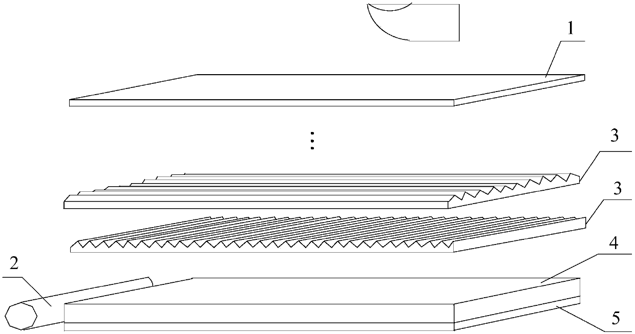
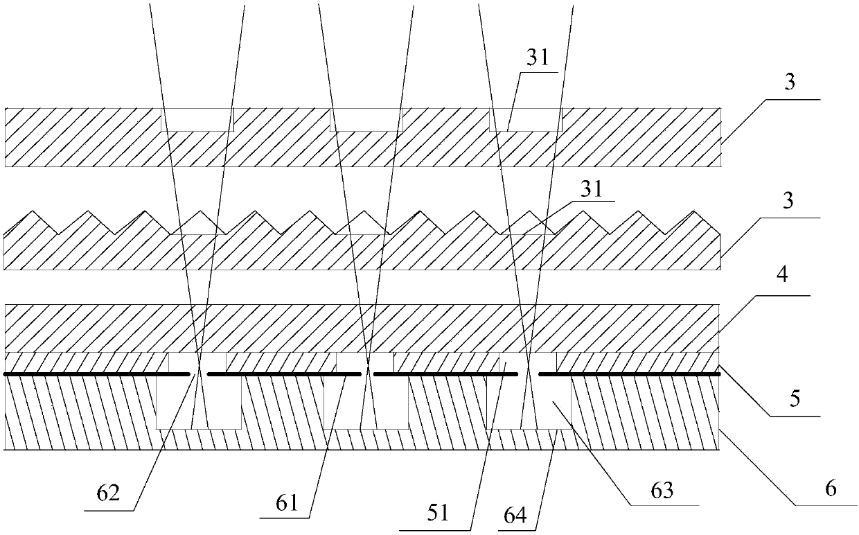
[0041] The collector 6 can collect fingerprint images by means of pinhole imaging. Such as figure 2 As shown, the collector 6 includes a mask 61, one side of the mask 61 is connected to the reflector 5, and an imaging hole 62 communicating with the first light-transmitting hole 51 is arranged in the mask 61. The other side of the plate 61 is provided with a cavity 63 communicating with the imaging hole 62, and the bottom of the cavity 63 is provided with a photosensitive device 64, and light can pass through the light-transmitting part 31, the first light-transmitting hole 51 and the The imaging hole 62 is directed to the photosensitive device 64 in the cavity 63, and the photosensitive device 64 may be a photoelectric conversion sensor. The first light transmission hole 51 and the imaging hole 62 may be in one-to-one correspondence.

[0042] The diameter of the first light transmission hole 51 is not smaller than the diameter of the imaging hole 62 . Due to process limita...

Embodiment approach 2

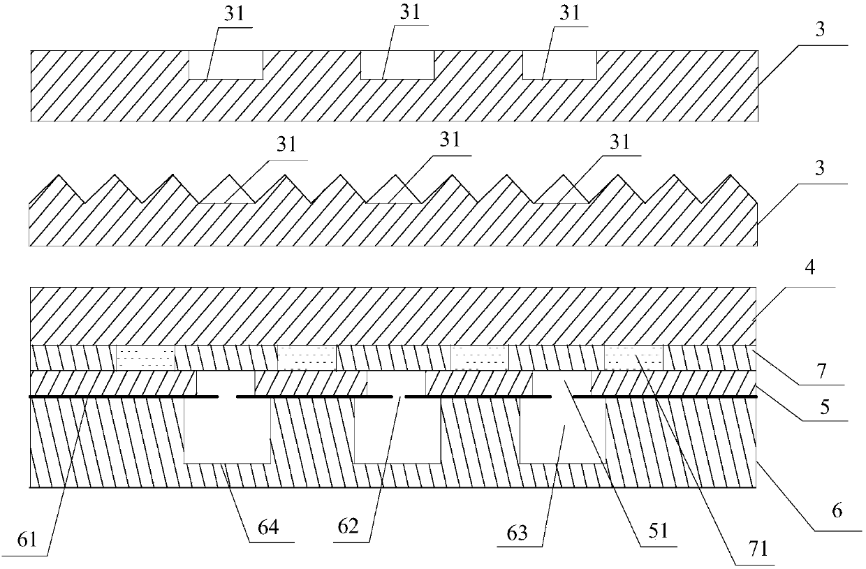
[0044] The collector 6 can collect fingerprint images by means of lens imaging. Such as Image 6 As shown, in something like figure 2 On the basis of the structure of the collector 6 shown, a lens 9 for converging light directed to the photosensitive device 64 may be provided at the imaging hole 62 . The lens 9 can be disposed on any side of the mask 61 , and the lens 9 can be a convex lens 9 or other types of lenses 9 . Such as Figure 5 As shown, the lenses 9 at the respective imaging holes 62 can be set independently, and the imaging holes 62 correspond to the lenses 9 one by one. or as Figure 7 As shown, a transparent medium 10 can be provided between the reflection plate 5 and the mask 61 , and the lens 9 corresponding to each imaging hole 62 is arranged on the transparent medium 10 , and the imaging holes 62 correspond to the lenses 9 one by one. The size of the imaging hole 62 in the first embodiment may be different from that in the second embodiment, and the de...

Embodiment approach 3

[0046] The collector 6 can collect fingerprint images through dense through holes. Such as Figure 8 As shown, the collector 6 includes a plurality of through holes 65 parallel to each other, the bottom of each of the through holes 65 is provided with a photosensitive device 64, and each of the first light-transmitting holes 51 communicates with at least one through hole 65 , the diameter of the through holes 65 is 0.5 microns to 50 microns, and the size of the collection area corresponding to each through hole 65 is the same as the size of the collected image. In order to make the size of the acquisition area corresponding to each through hole 65 the same as the size of the collected image, the diameter of the through hole 65 and the length of the through hole 65 can be set to an appropriate value, so that the through hole 65 receives parallel rays or approximately parallel light rays. of light. Since the through holes 65 are densely arranged, and each through hole 65 can c...


PUM


Abstract

The embodiment of the invention discloses a display screen which comprises a prism sheet, a light guide plate and a reflecting plate, wherein a light-transmitting part is arranged in the prism sheet; and a first light-transmitting hole corresponding to the light-transmitting part is formed in the reflecting plate, and light sequentially passes through the light-transmitting part, the light guide plate and the first light-transmitting hole. According to the embodiment of the invention, light rays used for collecting fingerprint images can sequentially pass through the light-transmitting part in the prism sheet, the light guide plate and the light-transmitting hole in the reflecting plate and are emitted to the photosensitive device in the collector, so that the under-screen fingerprint collection of the display screen is smoothly completed.

Description

technical field [0001] Embodiments of the present invention relate to the technical field of fingerprint identification under the screen, and in particular, to a display screen. Background technique [0002] Under-screen fingerprint recognition technology refers to a fingerprint recognition technology that collects fingerprints on the other side of the display screen through a collector set on one side of the display screen to complete fingerprint recognition. In the practical application of the fingerprint recognition technology under the screen, when a finger touches the display screen, the collector on the other side of the display screen can collect fingerprints, and then the fingerprint recognition is completed through the processor connected to the collector. [0003] Common display screens include liquid crystal display (Liquid Crystal Display, LCD) and organic light-emitting diode (Organic Light-Emitting Diode, OLED) screens. Compared with using an LCD screen to rea...

Claims


Application Information

Patent Timeline
Patent Type & Authority Applications(China)
IPC IPC(8): G06K9/00
CPCG06V40/1324G06V40/1318
Inventor 张明方
Owner VKANSEE (BEIJING) TECHNOLOGY CO LTD
Why Eureka
Try Eureka