Supercharge Your Innovation With Domain-Expert AI Agents!

Coordinate calibration method, calibration system and mechanical arm

A technology of coordinate calibration and manipulators, which is applied in manipulators, program-controlled manipulators, image analysis, etc., can solve the problems of precision dependence, long processing cycle, cumbersome operation, etc., and achieve strong applicability and flexibility, good consistency, and calibration high precision effect

Active Publication Date: 2021-09-21
JIHUA LAB
View PDF0 Cites 0 Cited by
  • Summary
  • Abstract
  • Description
  • Claims
  • Application Information

AI Technical Summary

Problems solved by technology

The error of the first method mainly comes from two aspects. One is that there is a large error when the manipulator fixes a sharp calibration tool (such as an awl). The tip coincides with the TCP (tool coordinate point) of the mechanical arm, and the second is that the alignment error of the human eye is large, the consistency is poor, and the operation is cumbersome
The second method has higher accuracy than the first method, but its accuracy depends on the calibration mold and its array. The calibration mold and its array not only have a long processing cycle, but also have wear and tear. The calibration process is also time-consuming and laborious, and the operation is cumbersome.
It can still be used when the manipulator and the worktable are on the same platform (there is no relative motion between the base of the manipulator and the workbench), but this method is no longer applicable when there is relative motion and frequent calibration is required

Method used


Image

  • Coordinate calibration method, calibration system and mechanical arm
  • Coordinate calibration method, calibration system and mechanical arm
  • Coordinate calibration method, calibration system and mechanical arm

Examples


Embodiment 1

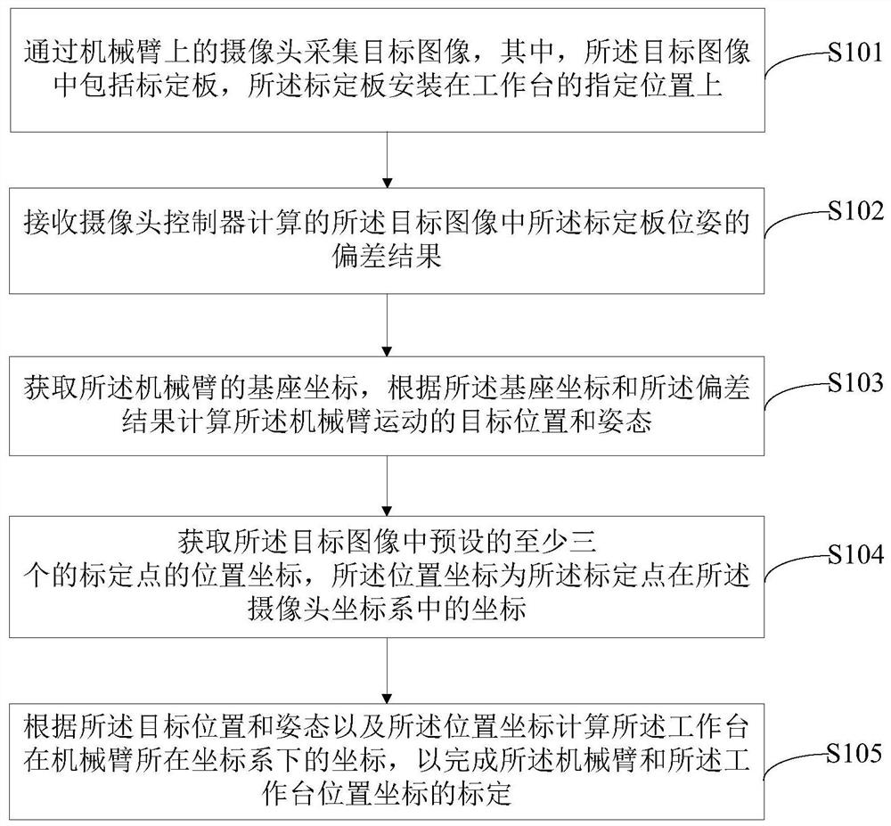
[0049] figure 1It is a schematic flowchart of a coordinate calibration method provided in Embodiment 1 of the present invention, and the method may include the following steps:

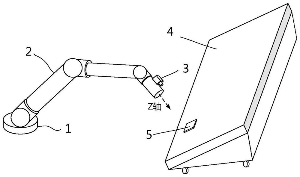
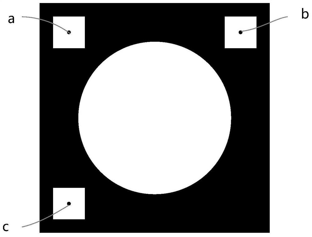
[0050] S101: Collect a target image through a camera on a robotic arm, wherein the target image includes a calibration plate, and the calibration plate is installed at a designated position on a workbench.

[0051] S102: Receive a deviation result of the calibration board pose in the target image calculated by the camera controller.

[0052] Optionally, before collecting the target image through the camera on the mechanical arm, it also includes:

[0053] Controlling the mechanical arm to move to a predetermined position, the predetermined position is set according to the position of the workbench.

[0054] Optionally, said collecting the target image through the camera on the mechanical arm includes:

[0055] controlling the mechanical arm to start moving from the predetermined position;

[0056]...

Embodiment 2

[0071] Image 6 The schematic diagram of the coordinate calibration system provided by Embodiment 2 of the present invention only shows the parts related to the embodiment of the present invention for the convenience of description.

[0072] The coordinate calibration system includes an upper computer 61, a mechanical arm controller 62, a mechanical arm 63, a camera controller 64 and a camera 65, and the upper computer 61 is connected to the mechanical arm controller 62 and the camera controller 64 respectively. Connect for communication. The above-mentioned parts can be connected and communicated by means of Ethernet or the like.

[0073] The camera 65 is installed on the mechanical arm 63, the mechanical arm controller 62 is used to control the mechanical arm 63 to move; the camera controller 64 is used to control the camera 65 to collect the target image;

[0074] When the coordinate positioning system is in operation: the target image is collected by the camera 65 on the...


PUM


Abstract

The present invention is applicable to the technical field of intelligent control, and provides a coordinate calibration method, a calibration system and a mechanical arm, wherein the coordinate calibration method includes collecting a target image through a camera on the mechanical arm; receiving the target image calculated by the camera controller The deviation result of the calibration board pose described in the above; obtain the base coordinates of the mechanical arm, calculate the target position and posture of the mechanical arm movement according to the base coordinates and the deviation result; obtain the target image Preset position coordinates of at least three calibration points; calculate the coordinates of the workbench in the coordinate system of the mechanical arm according to the target position and posture and the position coordinates, so as to complete the mechanical arm and the work Calibration of station position coordinates. The embodiment of the invention can automatically perform coordinate calibration between the mechanical arm and the workbench, with high calibration accuracy, strong applicability and flexibility; non-contact calibration using a visual method does not have the problem of mechanical wear.

Description

technical field [0001] The invention relates to the field of intelligent control, in particular to a coordinate calibration method, a calibration system and a mechanical arm. Background technique [0002] As the robotic arm is more and more widely used in industrial production and manufacturing, the robotic arm and its operating table are more and more on different platforms. In this case, the high-precision movement of the manipulator on the workbench must accurately calibrate the coordinates between the manipulator and the workbench, generally referring to the coordinates of the workbench plane under the coordinate system of the manipulator base. [0003] At present, there are mainly two methods of coordinate calibration between the manipulator and the workbench: one is to use a sharp calibration tool to move the manipulator to three points on the workbench, and align it with human eyes to obtain the corresponding coordinates point to determine the coordinate plane of the...

Claims


Application Information

Patent Timeline
Patent Type & Authority Patents(China)
IPC IPC(8): G06T7/70B25J9/10
CPCB25J9/10G06T7/70
Inventor 姜良旭余毅付云博曹策张立文
Owner JIHUA LAB
Features
  • R&D
  • Intellectual Property
  • Life Sciences
  • Materials
  • Tech Scout
  • Unparalleled Data Quality
  • Higher Quality Content
  • 60% Fewer Hallucinations
Learn More