Traffic light control method and device for adjusting signal conversion time based on photo recognition

A technology for converting time and adjusting signals, which is applied in the field of traffic management, and can solve problems such as troublesome installation and debugging, high failure rate, and low penetration rate, and achieve the effects of reducing the difficulty of installation and maintenance, alleviating road traffic congestion, and low cost

Inactive Publication Date: 2019-09-24
陈硕坚
View PDF8 Cites 2 Cited by
  • Summary
  • Abstract
  • Description
  • Claims
  • Application Information

AI Technical Summary

Problems solved by technology

These methods have the disadvantages of high cost, troublesome installation and debugging, and high failure rate, resulting in low penetration rate

Method used


Image

  • Traffic light control method and device for adjusting signal conversion time based on photo recognition
  • Traffic light control method and device for adjusting signal conversion time based on photo recognition
  • Traffic light control method and device for adjusting signal conversion time based on photo recognition

Examples


Embodiment 1

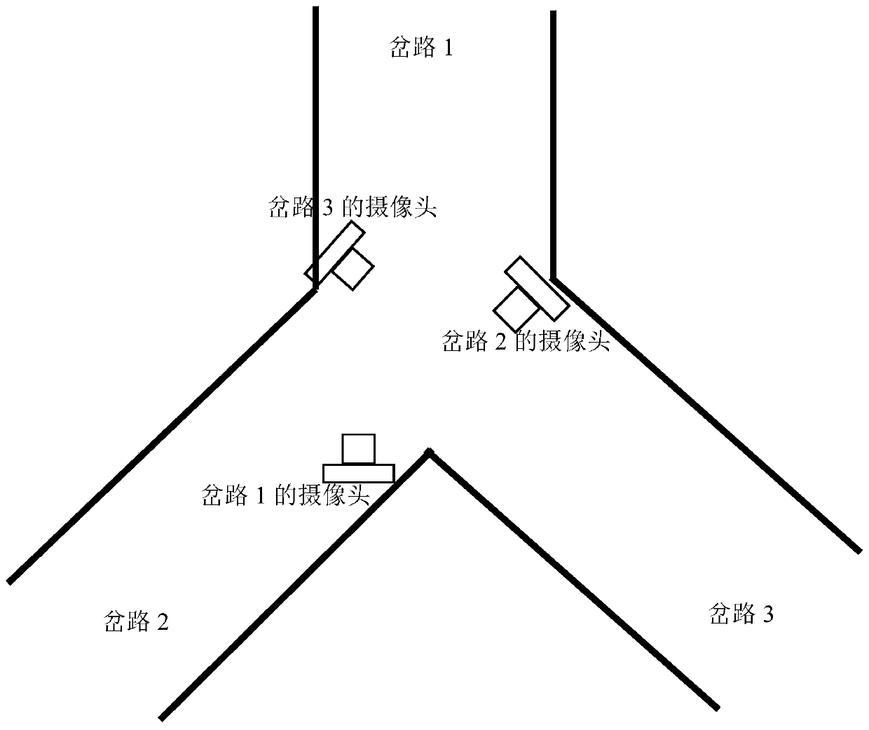
[0033] Embodiment 1: An example where the present invention is applied to a three-way intersection. figure 2 It is a schematic diagram of camera installation at a fork in the road. A group of 3 cameras are installed in total. Each camera is aimed at a fork in the road. The height of the camera is not less than 4 meters.

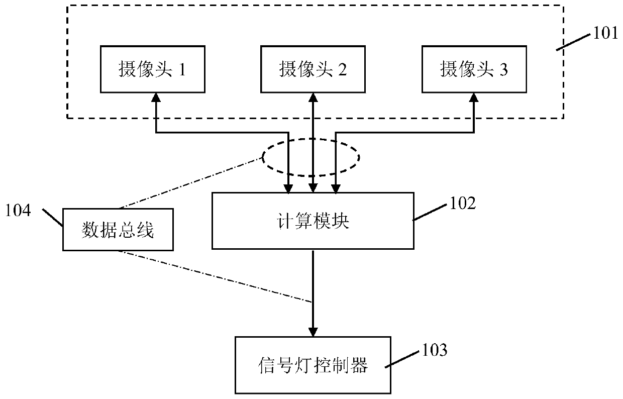
[0034] image 3 It is a structural diagram of the calculation and control device adopted in Embodiment 1. The complete set includes:

[0035] Module 101: Install a group of 3 cameras at the three-way intersection.

[0036] Module 102: a computing module, including: a storage unit for storing instructions, and at least one processor coupled to the storage unit; wherein, when the at least one processor executes the instructions, the The instructions cause the processor to perform the method as claimed in claims 1-3.

[0037] Module 103: a controller for controlling the traffic lights to turn on and off.

[0038] Module 104: a data bus used for communicati...

Embodiment 2

[0049] Figure 5 For the schematic diagram of Embodiment 2 of the present invention applied to a five-fork intersection, a group of five cameras is installed, each camera is aimed at a fork, and the height of the camera is not less than 4 meters.

[0050]The computing and control devices used in Embodiment 2 are similar to those in Embodiment 1 (but the number of cameras is changed from 3 to 5), and will not be repeated here.

[0051] The calculation and control device of embodiment 2 comprises the following steps during operation:

[0052] Step 201: When the crosswalk signal light is green, use 5 cameras to take photos of 5 branch roads. At this time, the cars on the fork road are all in a state of waiting for traffic.

[0053] Step 202: Use a computer to identify and count the number of cars waiting to pass in the five branch road photos according to the photos taken in step 201. When identifying and counting the number of cars, feature extraction algorithms such as princ...


PUM


Abstract

The invention provides a method and device for detecting the traffic flow at an intersection and dynamically adjusting the conversion time of traffic lights according to the traffic flow by using the photo recognition technology. The method comprises the following step: at a road intersection, enabling a camera to take pictures of all branch roads; identifying and counting the number of vehicles waiting for passing on each branch road according to the pictures; calculating the optimal conversion time of each group of traffic lights according to the number of the waiting vehicles on each branch road; and controlling the on-off of the traffic lights according to the optimal conversion time. The invention further provides a calculation and control device for executing the method. Compared with traditional traffic flow detection equipment, the device can detect the traffic flow of each branch road of the intersection only by adopting a common camera, and achieves the dynamic adjustment of the traffic time. Compared with other methods, the method has the advantages of being low in cost, easy to install, low in failure rate and the like, the road use efficiency can be improved, and traffic jam is relieved.

Description

technical field [0001] The invention relates to the control technology and device of road traffic signal lamps in the field of traffic management. More specifically, it relates to a method and a device for how to identify and count the traffic flow at each intersection at low cost, and dynamically adjust the switching time of road traffic lights according to the traffic flow. Background technique [0002] At present, most of the signal lights at intersections in our country are switched according to the preset switching time when changing the signal. The distribution of travel time is unreasonable, some fork roads are congested, and some fork roads are too idle. [0003] There are also a small number of traffic intersections that use the technology of dynamically allocating passing time. The key to dynamic allocation of passing time is to detect the traffic flow of different branch roads. At present, the measuring equipment used to detect traffic flow mainly includes: coi...

Claims


Application Information

Patent Timeline
Patent Type & Authority Applications(China)
IPC IPC(8): G08G1/08G08G1/01G08G1/04G08G1/065
CPCG08G1/0145G08G1/04G08G1/065G08G1/08
Inventor 陈硕坚
Owner 陈硕坚
Why Eureka
Try Eureka