Check patentability & draft patents in minutes with Patsnap Eureka AI!

Pulse-width modulation controller and tri-state voltage generation method

一种脉宽调变、产生方法的技术,应用在脉冲持续时间/宽度调制、多个状态的逻辑电路、电气元件等方向,能够解决切换效能不佳等问题,达到缩短耗费的时间的效果

Active Publication Date: 2019-09-24
UPI SEMICON CORP
View PDF11 Cites 1 Cited by
  • Summary
  • Abstract
  • Description
  • Claims
  • Application Information

AI Technical Summary

Problems solved by technology

[0004] However, figure 1 The output of the buffer BF will be affected by the resistance-capacitance effect produced by the parasitic capacitance CPS in the driving circuit 12 and the external setting resistance RSET, therefore, as figure 2 As shown, the voltage level of the output signal Q of the existing PWM takes a period of time (for example, 180ns) before being pulled to a fixed third-state voltage level, resulting in poor switching performance.

Method used


Image

  • Pulse-width modulation controller and tri-state voltage generation method
  • Pulse-width modulation controller and tri-state voltage generation method
  • Pulse-width modulation controller and tri-state voltage generation method

Examples


Embodiment Construction

[0069] Reference will now be made in detail to the exemplary embodiments of the present invention, examples of which are illustrated in the accompanying drawings. Components / components with the same or similar numbers used in the drawings and the embodiments are used to represent the same or similar parts.

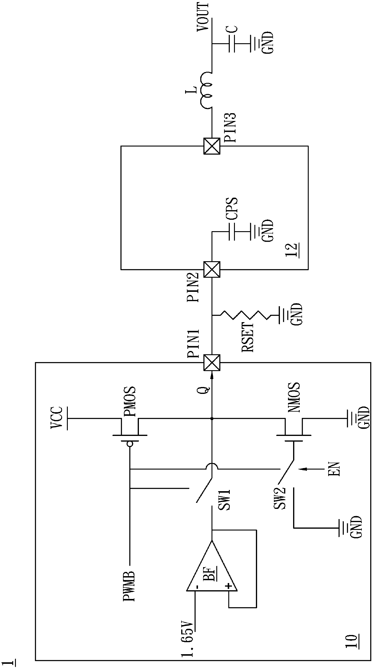
[0070]A specific embodiment according to the present invention is a pulse width modulation controller. In this embodiment, the PWM controller applied in the power supply circuit first quickly pulls the voltage level of the PWM signal entering the third state to the voltage level of the third state by means of resistor division quasi-interval, and then maintain the voltage level voltage of the PWM signal in the third-state voltage level interval through the buffer, so as to effectively shorten the time it takes for the PWM signal to enter the third state, and reduce the The impact of the large current generated by the resistance voltage divider on the driving circuit coupl...


PUM


Abstract

A pulse-width modulation (PWM) controller including an output pin, a temporary voltage generation circuit and a tri-state voltage generation circuit is disclosed. The temporary voltage generation circuit includes a voltage-dividing unit and a control unit. The voltage-dividing unit is coupled to the output pin and the control unit respectively. The control unit receives an enable signal and a PWM signal. The tri-state voltage generation circuit is coupled to the temporary voltage generation circuit and the output pin and receives the enable signal, the PWM signal and a tri-state input voltage. When the PWM controller is operated in a tri-state mode, the control unit controls the voltage-dividing unit to provide a temporary voltage to the output pin according to the enable signal and PWM signal, and then the tri-state voltage generation circuit provides a tri-state voltage to the output pin according to the enable signal and PWM signal.

Description

technical field [0001] The present invention relates to a power supply circuit, in particular to a pulse width modulation controller and a method for generating a third-state voltage. Background technique [0002] In the operation of the existing power supply circuit, in order to reduce the switching energy loss, there will be a period of time when the zero current (ZeroCurrent, ZC) controls both the upper bridge switch and the lower bridge switch to be non-conductive. At this time, the PWM signal has a voltage level between a high voltage level (High-level) and a low voltage level (Low-level), which is called a third state (Tri-state). [0003] Please refer to figure 1 , figure 1 It is a schematic diagram of an existing pulse width modulation controller 1 . Such as figure 1 As shown, in the normal operation state, the pulse width modulation signal generator 10 controls the conduction or closure of the operation switch PMOS through the pulse width modulation signal PWMB,...

Claims


Application Information

Patent Timeline
Patent Type & Authority Applications(China)
IPC IPC(8): H02M1/088
CPCH02M1/088H03K7/08Y02B70/10H02M1/0048H03K19/0002
Inventor 张志廉赖敏瑞
Owner UPI SEMICON CORP
Features
  • R&D
  • Intellectual Property
  • Life Sciences
  • Materials
  • Tech Scout
  • Unparalleled Data Quality
  • Higher Quality Content
  • 60% Fewer Hallucinations
Learn More