Magnetic tape recording and/or reproduction apparatus and its reel braking mechanism

A tape recording and braking mechanism technology, which is applied in the direction of record carrier drive mechanism, data recording, recording information storage, etc., can solve the problems of non-static, tape slack, etc., and achieve the effect of small overall thickness

Inactive Publication Date: 2003-03-05
PANASONIC CORP
View PDF3 Cites 0 Cited by
  • Summary
  • Abstract
  • Description
  • Claims
  • Application Information

AI Technical Summary

Problems solved by technology

More precisely, due to the difference in braking force, the take-up reel brakes instantaneously to stop, but the supply reel takes a long time to brake to a stop, resulting in the occurrence of magnetic tape between the cores in the casse

Method used


Image

  • Magnetic tape recording and/or reproduction apparatus and its reel braking mechanism
  • Magnetic tape recording and/or reproduction apparatus and its reel braking mechanism
  • Magnetic tape recording and/or reproduction apparatus and its reel braking mechanism

Examples


no. 1 Embodiment approach - pic 1 to 3

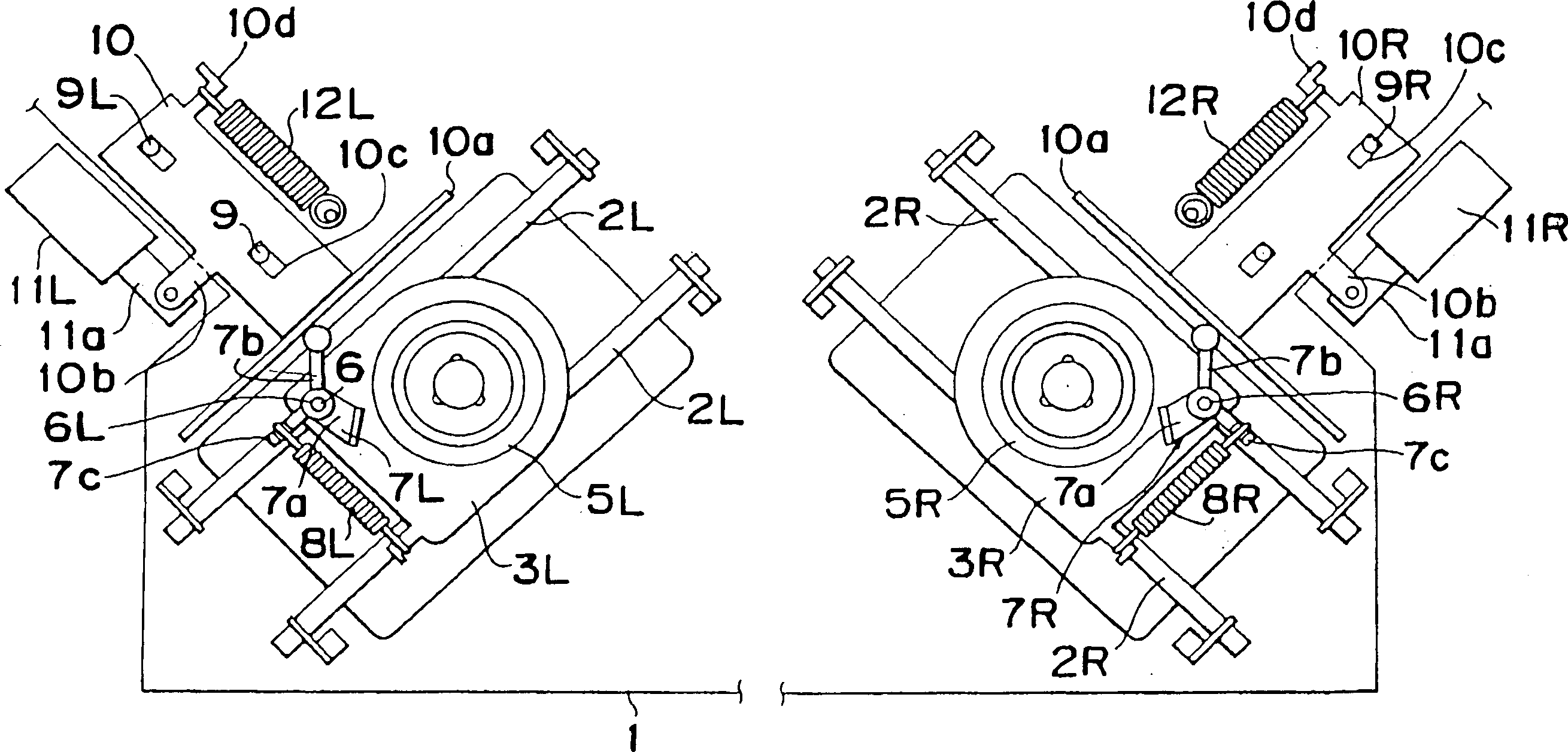
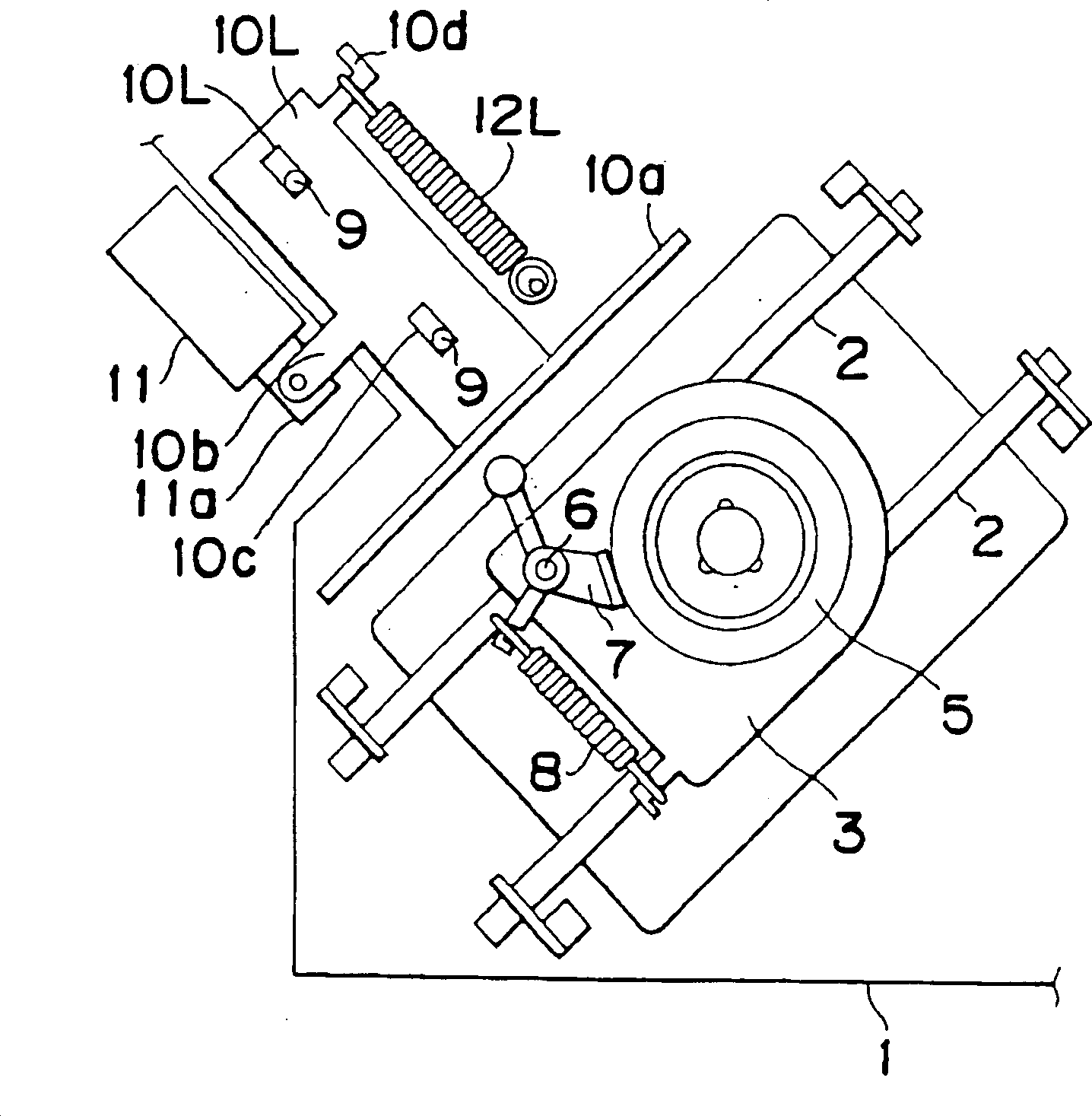
[0045] figure 1 A video recorder shown in includes a reel support bottom case 1 on which two pairs of parallel guide rods 2 are mounted. One pair of parallel guide rods 2L and the other pair of parallel guide rods 2R are mounted on the bottom case 1 so as to intersect at an imaginary straight line away from the corresponding rotation axes connecting the supply reel 5L and the take-up reel 5R.

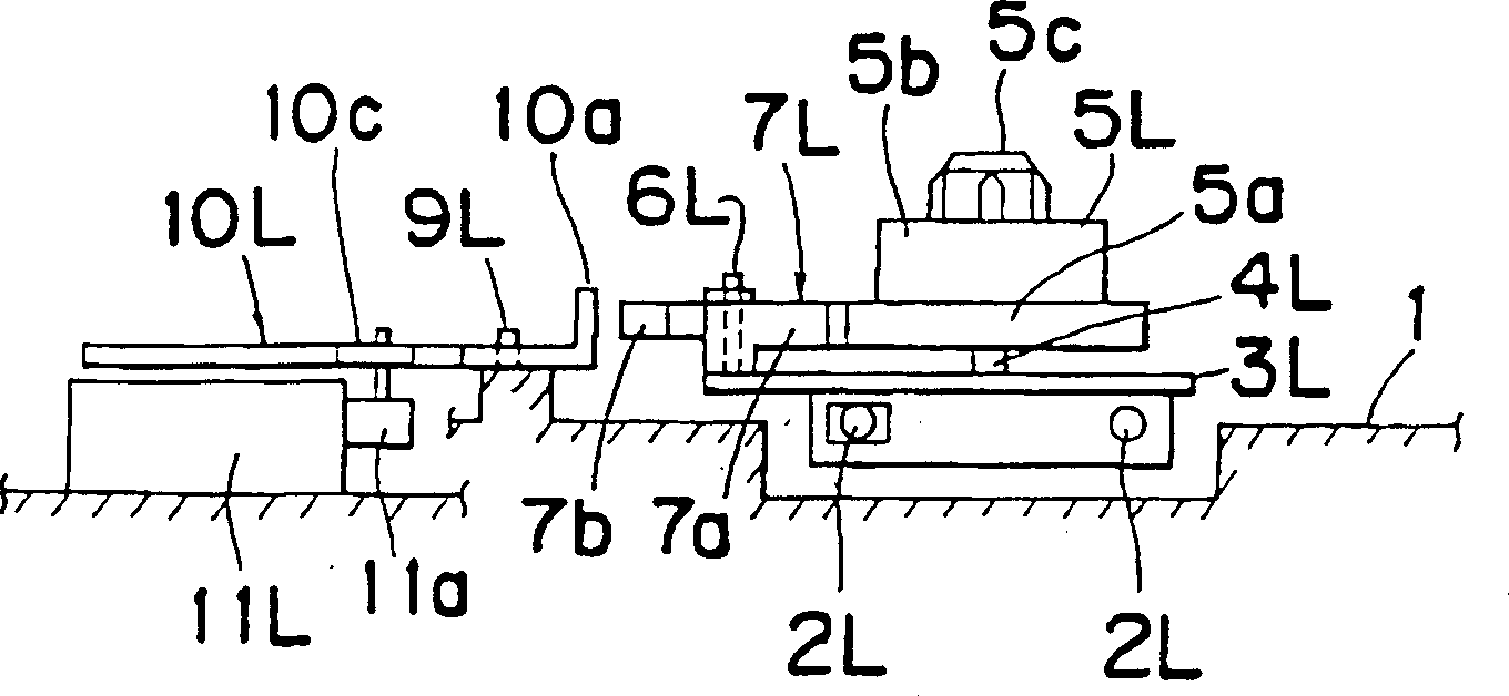
[0046] The supply reel 5L is pivotally connected to the support base 3L of the supply reel through the pin shaft 4L, and the pin shaft 4L is integrated with the support base 3L and connected coaxially with the supply reel 5L. Similarly, the take-up reel 5R is connected through the pin shaft 4R is rotatably fixed on the tape reel support base 3R, and the bolt shaft is integrated with the support base 3R and coaxially connected with the tape reel 5R. Supply reel 5L and take-up reel 5R are movably mounted in known manner on parallel guides 2L and 2R, respectively, and are movable between...

no. 2 approach - pic 5 to 8

[0068] In the foregoing embodiments, the pushing means of each of the supply reel 5L and the take-up reel 5R has been described as including the sliders 10L and 10R integrally connected with the respective pushing pieces 10a. However, in the second preferred embodiment of the present invention, the urging means of each of the supply reel 5L and the take-up reel 5R comprises a generally elongated plate-like urging piece which, in response to movement of the rod-like core, moves around Rotate along an axis parallel to the length direction of the elongated plate-shaped push piece. The push means used in the reel brake mechanism connected only to the supply reel 5L will be described in detail below.

[0069] The opposite ends of the elongated plate-like pushing means 10a used in the second embodiment of the present invention are bent perpendicularly to the main body of the pushing piece 10a. The slender plate-like push piece 10a is installed on the bottom case 1, and its opposite...


PUM


Abstract

A reel braking mechanism for a magnetic tape recording and/or reproducing apparatus includes first and second reels (5L, 5R), and first and second reel support bases (3L, 3R) for rotatably supporting thereon the first and second reels, respectively the first and second reels are movable together with the first and second reel support bases (3L, 3R) between a first cassette position corresponding to a hub-to-hub distance in a standard tape cassette and a second cassette position corresponding to a hub-to-hub distance for a compact tape cassette. The reel braking mechanism includes a brake lever (7L, 7R) movably mounted on each of the first and second reel support bases (3L, 3R) and having a first arm (7a) engageable with the corresponding reel and a second arm (7b). The brake lever is movable between an engaged position in which the first arm (7a) is engaged with the corresponding reel to hold the reel and a disengaged position in which the first arm (7a) is disengaged from the corresponding reel. A pushing element (10L, 10R, 10a, 11L, 11R; 10L, 10R, 10a, 11L, 11R, 24L, 14R; 10L, 10R, 11L, 11R, 30L, 30R) for pushing the second arm (7b), regardless of the position of the corresponding reel, to urges the brake lever (7L, 7R) towards the engaged position to thereby cause the first arm (7a) to be brought into frictional engagement with the corresponding reel.

Description

field of invention [0001] The present invention relates generally, though not exclusively, to a magnetic tape recording and / or playback device, such as a video recorder and, more particularly, to a reel mechanism for use with a video recorder, after the cassette is loaded into the video recorder , a mechanism used to brake at least one of the take-up reel and the supply reel to prevent a section of tape located between the two cores from becoming loose. Background technique [0002] Video recorders known in the art are capable of loading tape cassettes of different sizes, selectively one cassette at a time. For example, there are two types of existing VHS video tapes now on the market, a standard type and a compact type, and the sizes of their cassettes are different from each other. Standard size video cassettes are widely used in home video recorders connected to television receivers, while pocket size video tapes are mainly used in pocket and ca...

Claims


Application Information

Patent Timeline
IPC IPC(8): G11B15/22G11B15/32G11B25/06
CPCG11B25/066G11B15/32G11B15/22
Inventor 宫胁慎典
Owner PANASONIC CORP
Why Eureka
Try Eureka