
Inductor wire end automatic paint removal device

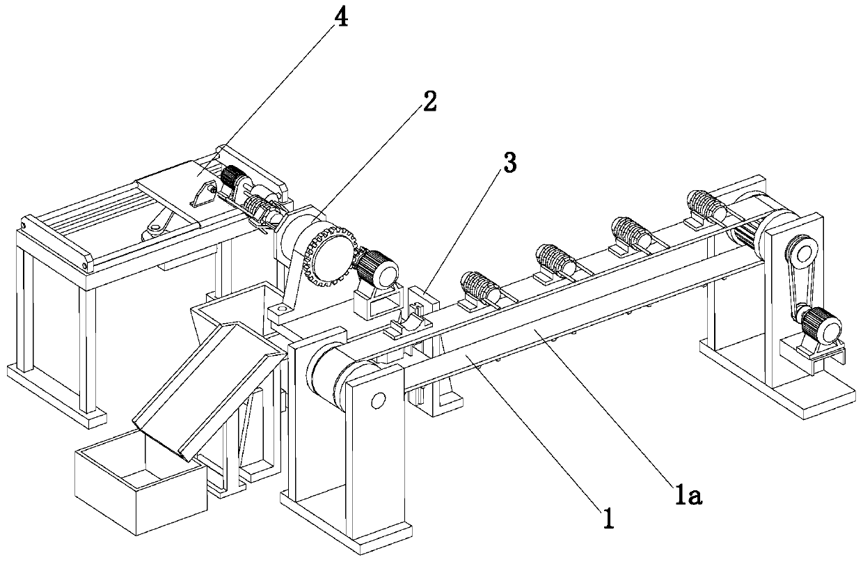
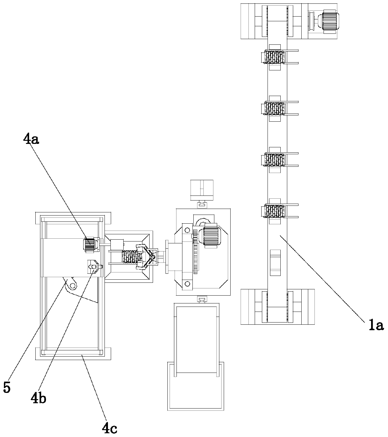
A technology for inductors and wire ends, which is applied in the field of automatic paint removal devices for inductor wire ends, can solve problems such as inability to remove paint from inductor wire ends, and achieve the effects of high degree of automation, reduced labor, and avoidance of potential safety hazards.

Active Publication Date: 2019-09-27
湖南俊宇电子科技有限公司
View PDF18 Cites 2 Cited by
  • Summary
  • Abstract
  • Description
  • Claims
  • Application Information

AI Technical Summary

Problems solved by technology

[0003] The purpose of the present invention is to provide an automatic paint removal device for inductor wire ends to solve the technical problem in the prior art that the paint cannot be automatically removed for inductor wire ends

Method used


Image

  • Inductor wire end automatic paint removal device
  • Inductor wire end automatic paint removal device
  • Inductor wire end automatic paint removal device

Examples


Embodiment Construction

[0032] The technical solutions of the present invention will be clearly and completely described below in conjunction with the accompanying drawings. Apparently, the described embodiments are some of the embodiments of the present invention, but not all of them.

[0033] The components of the embodiments of the invention generally described and shown in the figures herein may be arranged and designed in a variety of different configurations. Accordingly, the following detailed description of the embodiments of the invention provided in the accompanying drawings is not intended to limit the scope of the claimed invention, but merely represents selected embodiments of the invention.

[0034]Based on the embodiments of the present invention, all other embodiments obtained by persons of ordinary skill in the art without making creative efforts belong to the protection scope of the present invention.

[0035] In the description of the present invention, it should be noted that the ...


PUM


Abstract

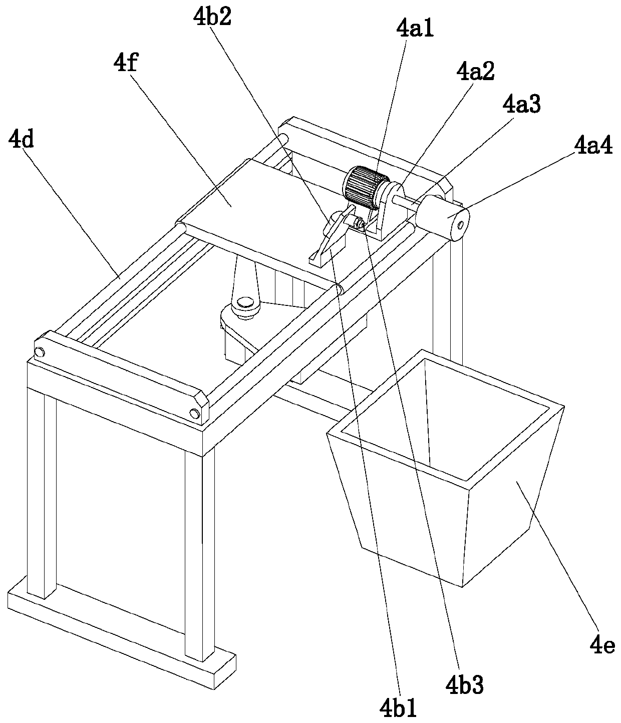
The invention discloses an inductor wire end automatic paint removal device and belongs to the technical field of inductor production equipment. The inductor wire end automatic paint removal device comprises an inductor feeding mechanism, an inductor clamping mechanism, a position regulation mechanism and a wire end paint removal mechanism. The wire end paint removal mechanism comprises a paint removal component, a waste residue cleaning component, a sliding plate, a rack and a material moving component. The paint removal component and the waste residue cleaning component are both arranged on the top of the sliding plate. The material moving component is arranged below the sliding plate. The rack is provided with two horizontal supporting rods. The sliding plate is slidably arranged on the two supporting rods in a sleeving mode. The inductor wire end automatic paint removal device can realize feeding, paint removal, cleaning and discharging on inductors and is high in automation degree. Manual operation of a worker is not needed. Moreover, the inductor wire end automatic paint removal device can enable wire ends on the inductors to rotate through an angle adjustment assembly and can conduct paint removal treatment on the wire ends of the inductors in different azimuths through a paint removal wheel.

Description

technical field [0001] The invention relates to the technical field of inductor production equipment, in particular to an automatic paint removal device for inductor wire ends. Background technique [0002] Inductors are one of the three major electronic components in the electronics industry. With the rapid development of SMT (Surface Mount Technology), the demand for SMD (Surface Mount Electronic Components) has also increased significantly. In the production of traditional chip inductors, the first process is to manually or mechanically wind the enameled wire with a certain number of turns and specifications on the magnetic core; the next process is to mechanically remove the insulating varnish from the wire ends of the enameled wire leads. , the traditional method of removing paint from the inductor wire ends is manually operated. Manually using a grinding wheel or grinding paper to remove the paint from the inductor wire ends is time-consuming and laborious, and the ma...

Claims


Application Information

Patent Timeline
Patent Type & Authority Applications(China)
IPC IPC(8): B08B1/02B08B3/02B08B3/08B08B13/00B08B1/20
CPCB08B3/02B08B3/08B08B13/00B08B1/20
Inventor 李衡陈德华金吕辉肖猛
Owner 湖南俊宇电子科技有限公司
Learn More