
Anti-jumper wire take-up equipment for processing bare copper filaments

A wire take-up equipment and filament technology, which is applied in the field of anti-jump wire take-up equipment, can solve the problem of bare copper filaments winding to the outside of the take-up reel or even being involved in the motor shaft, failure of bare copper filaments to take up, and bare copper The problem of wire jumper and other problems can be solved, so as to achieve the effect of continuing to take up the wire, preventing the copper wire from falling off, and avoiding jumping

Active Publication Date: 2019-09-27
江西源广顺科技协同创新有限公司
View PDF8 Cites 4 Cited by
  • Summary
  • Abstract
  • Description
  • Claims
  • Application Information

AI Technical Summary

Problems solved by technology

[0002] In the production of copper wire, raw materials such as copper rods need to be drawn and formed to form bare copper filaments. Copper filaments are wound and taken up, and the bare copper filaments are not guided and limited during the takeup process, which may easily lead to wire jumping due to equipment vibration when the bare copper filaments are wound, resulting in the bare copper filaments being entangled to the take-up reel The outer side is even involved in the motor shaft, which eventually leads to the failure of the bare copper filament to be taken up. Jumper take-up equipment is used to solve the above problems

Method used


Image

  • Anti-jumper wire take-up equipment for processing bare copper filaments
  • Anti-jumper wire take-up equipment for processing bare copper filaments
  • Anti-jumper wire take-up equipment for processing bare copper filaments

Examples


Embodiment Construction

[0017] The following will clearly and completely describe the technical solutions in the embodiments of the present invention with reference to the accompanying drawings in the embodiments of the present invention. Obviously, the described embodiments are only some, not all, embodiments of the present invention. Based on the embodiments of the present invention, all other embodiments obtained by persons of ordinary skill in the art without making creative efforts belong to the protection scope of the present invention.

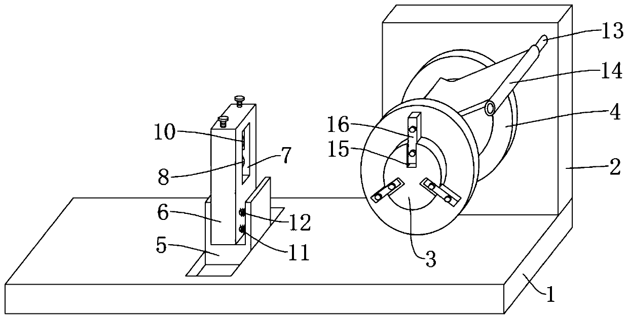
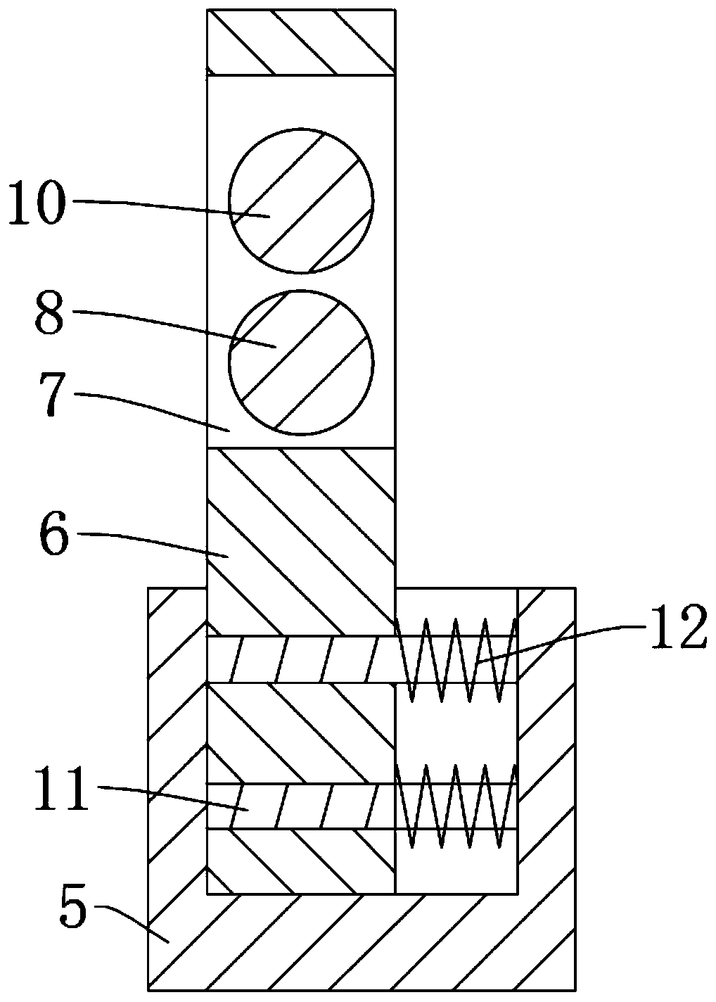
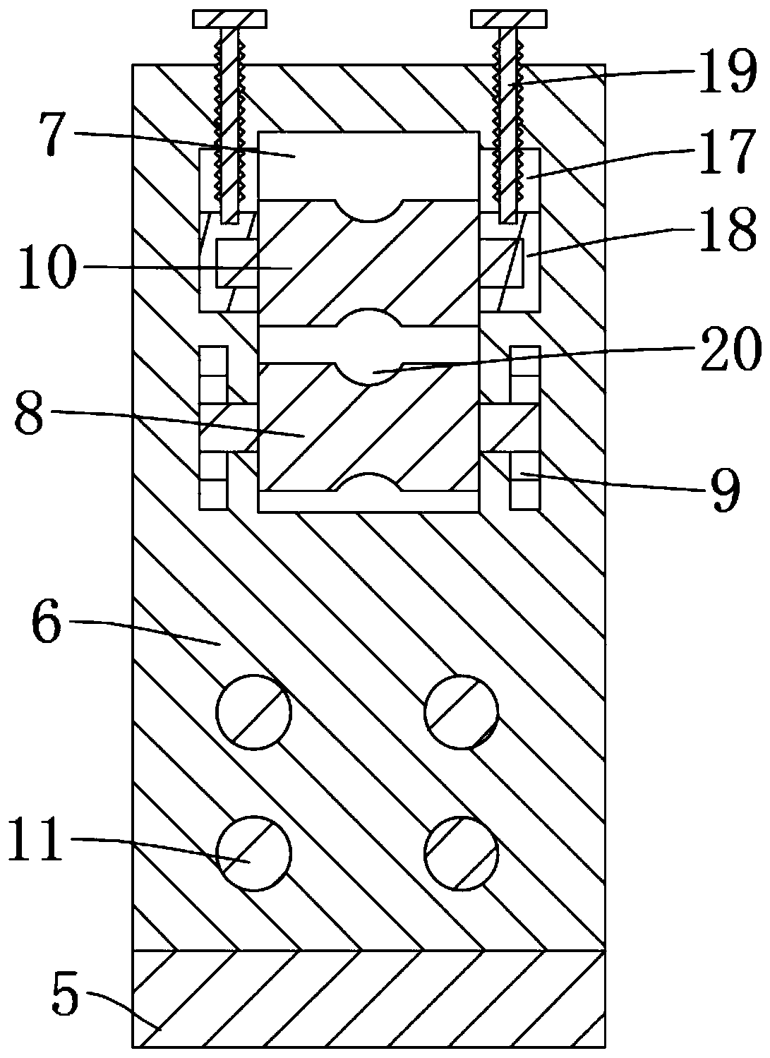
[0018] see Figure 1-4 , the present invention provides a technical solution: an anti-jump wire take-up device processed by bare copper filaments, including a base 1, a fixed plate 2 is fixedly installed on one end side wall of the base 1, and a drive shaft is rotatably socketed on the fixed plate 2 3. The drive shaft 3 is put on the receiving reel 4, and the top of the fixed plate 2 is fixedly installed with the fixed rod 13. The fixed rod 13 is fixedly sleev...


PUM


Abstract

The invention discloses anti-jumper wire take-up equipment for processing bare copper filaments. The equipment comprises a base, a fixing plate is mounted at one end of the base, the fixing plate is in sleeved connection with a driving shaft which is in sleeved connection with a wire take-up disc, a fixing rod is mounted at the top of the fixing plate, the fixing rod is in sleeved connection with a pressing sheet, the pressing sheet is pressed on the wire take-up disc, a U-shaped seat is clamped at the other end of the base, and an inner cavity of the U-shaped seat is clamped with a mounting plate. A guide rod is installed between two side plates of the U-shaped seat, the bottom of the mounting plate is in sleeved connection with the guide rod, the guide rod is in sleeved connection with a spring, a mounting groove is formed in the top of the mounting plate, the bottom of the mounting groove is in sleeved connection with a fixing roller, the top of the side wall of the mounting groove is in sleeved connection with an anti-drop roller, an anti-loosening mechanism is installed between the fixing roller and the inner wall of the mounting groove, and an anti-loosening mechanism is installed between the driving shaft and the fixing plate. The anti-drop roller and the fixing roller are used for guiding and limiting the copper filaments and compressing the copper filaments, and the spring always gives the mounting plate an elastic force far away from the take-up disc, so that the copper filaments between the mounting plate and the take-up disc are always tightened, and the copper filaments are prevented from jumping.

Description

technical field [0001] The invention relates to the technical field of copper wire production, in particular to an anti-jump wire take-up device for processing bare copper filaments. Background technique [0002] In the production of copper wire, raw materials such as copper rods need to be drawn and formed to form bare copper filaments. Copper filaments are wound and taken up, and the bare copper filaments are not guided and limited during the takeup process, which may easily lead to wire jumping due to equipment vibration when the bare copper filaments are wound, resulting in the bare copper filaments being entangled to the take-up reel The outer side is even involved in the motor shaft, which eventually leads to the failure of the bare copper filament to be taken up. Jumper wire take-up equipment is used to solve the above problems. Contents of the invention [0003] The object of the present invention is to provide an anti-jump wire take-up device for processing bare...

Claims


Application Information

Patent Timeline
IPC IPC(8): B21C47/04B21C47/06
CPCB21C47/003B21C47/04B21C47/06
Inventor 李钢易晓勇朱丽榆
Owner 江西源广顺科技协同创新有限公司
Learn More