
Butt joint type automatic double-spindle numerical control machine tool for polygon turning

A CNC machine tool and docking technology, applied in the field of parts processing, can solve the problems of troublesome cleaning, pollution, serious pollution, etc., and achieve the effect of reducing the workload

Active Publication Date: 2019-09-27
兰溪瑞鼎机床股份有限公司
View PDF8 Cites 2 Cited by
  • Summary
  • Abstract
  • Description
  • Claims
  • Application Information

AI Technical Summary

Problems solved by technology

[0002] At present, the common dual-spindle CNC machine tools on the market are fixed with a row of tool holders in the middle of the base, and a spindle that can move back and forth, left and right is fixed on both sides of the tool row, and a clamping device is fixed on each spindle. The parts on the two spindles are processed in contact with different cutter heads in the row of cutters, so that the parts can complete two different types of processing at the same time; but when the parts are processed by such two spindles, the cutting waste will splash to the ground and the base The position between the base and the sliding seat causes greater pollution; the ground and the base need to be cleaned manually, and the structure of the position between the base and the sliding seat is more complicated, and the cleaning is more troublesome, which will lead to greater labor intensity for the staff
Therefore, the existing dual-spindle CNC machine tools have the problems of serious pollution and high labor intensity.

Method used


Image

  • Butt joint type automatic double-spindle numerical control machine tool for polygon turning
  • Butt joint type automatic double-spindle numerical control machine tool for polygon turning
  • Butt joint type automatic double-spindle numerical control machine tool for polygon turning

Examples


Embodiment Construction

[0023] The present invention will be further described below in conjunction with the accompanying drawings and embodiments, but not as a basis for limiting the present invention.

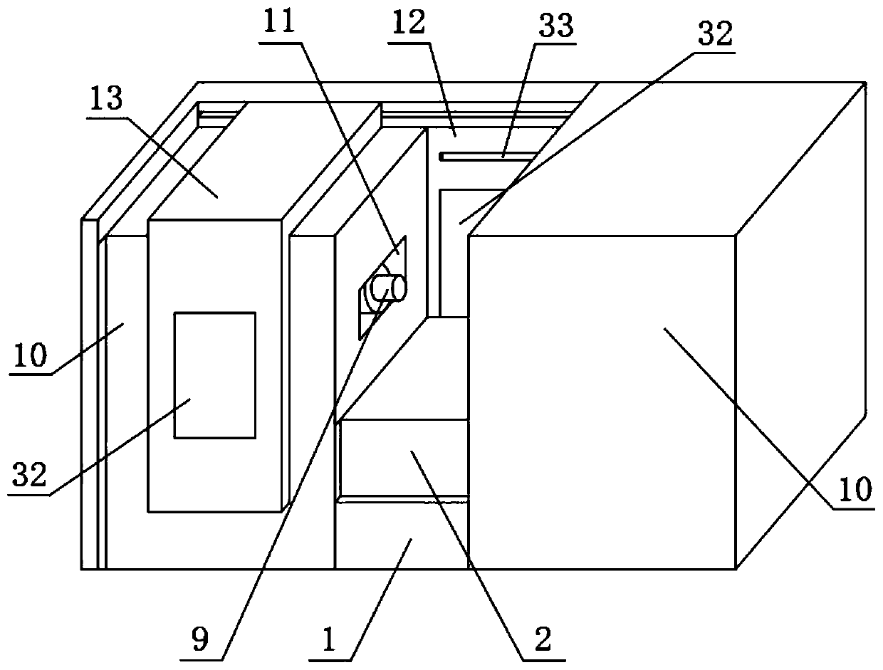
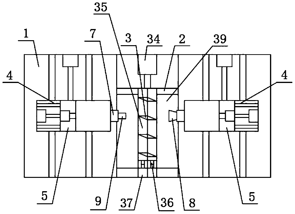
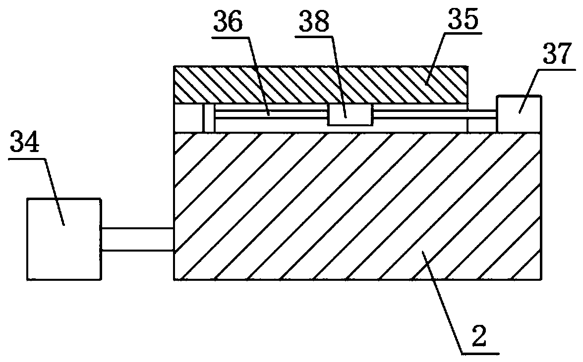
[0024] Example. Dockable automatic dual-spindle CNC machine tool for polygon turning, constituted as Figures 1 to 7 As shown, including the base 1, the middle part of the base 1 is provided with a knife row seat 2, and both sides of the top of the knife row seat 2 are fixed with a row of knives 3; Sliding seat 4, each horizontal sliding seat 4 is all horizontally slidably set with base 1, and the sliding direction of each horizontal sliding seat 4 is all parallel to row knife seat 2; Sliding seat 5, the sliding direction of each vertical sliding seat 5 is all perpendicular to row tool holder 2; One end of the tool holder 2 is respectively fixed with an outer chuck 8 and an inner support chuck 9; the base 1 is provided with an outer cover 10 at the positions corresponding to both sides of the row ...


PUM


Abstract

The invention discloses a butt joint type automatic double-spindle numerical control machine tool for polygon turning. The machine tool comprises a base, wherein a gang tool holder is arranged in the middle of the base, transverse sliding bases are arranged on the positions, corresponding to the two sides of the gang tool holder, of the base, each transverse sliding seat is provided with a vertical sliding seat, each vertical sliding seat is provided with a spindle, the two spindles are fixedly provided with an outer clamp cylinder clamp and an inner support clamp head, outer covers are arranged at the positions, corresponding to the two sides of the gang tool holder, of the base, horizontal open grooves are formed in the positions, corresponding to the outer clamp cylinder clamp and the inner support clamp head, of the two outer covers, a vertical baffle is fixed at the sides, corresponding to the open grooves, between the two outer covers, and an inverted L-shaped door cover which is horizontally and slidably arranged on the outer covers is arranged on one side of the baffle. The machine tool not only can reduce environmental pollution, but also has the advantages of being small in labor intensity, convenient in part clamping, high in working efficiency, strong in part clamping stability and long in service life.

Description

technical field [0001] The invention relates to the field of parts processing, in particular to a dockable automatic double-spindle numerical control machine tool for polygonal turning. Background technique [0002] At present, the common dual-spindle CNC machine tools on the market are fixed with a row of tool holders in the middle of the base, and a spindle that can move back and forth, left and right is fixed on both sides of the tool row, and a clamping device is fixed on each spindle. The parts on the two spindles are processed in contact with different cutter heads in the row of cutters, so that the parts can complete two different types of processing at the same time; but when the parts are processed by such two spindles, the cutting waste will splash to the ground and the base The position between the base and the sliding seat causes greater pollution; the ground and the base need to be cleaned manually, and the structure of the position between the base and the slid...

Claims


Application Information

Patent Timeline
IPC IPC(8): B23B9/10B23B21/00B23Q11/08
CPCB23B9/00B23Q11/08
Inventor 郑伟民杨翠勤
Owner 兰溪瑞鼎机床股份有限公司
Learn More