Check patentability & draft patents in minutes with Patsnap Eureka AI!

Continuous reciprocating type pushing device

A pushing device and reciprocating technology, which is applied in the field of continuous reciprocating material pushing device, can solve the problems of reducing the working efficiency of the carton packaging machine and achieve the effects of simple structure, reduced size and increased stability

Active Publication Date: 2019-09-27
ZHEJIANG SCI-TECH UNIV
View PDF8 Cites 0 Cited by
  • Summary
  • Abstract
  • Description
  • Claims
  • Application Information

AI Technical Summary

Problems solved by technology

[0003] The pushing device of the traditional carton packaging machine only completes the process of pushing the material into the carton in a straight line by the pushing head and exiting the pushing head in a straight line with no load. Since the pushing head of the traditional pushing device only makes a linear motion perpendicular to the direction of the conveyor belt, so When the pushing device is working, the conveyor belt must be stationary to prevent the interference between the two movements, which greatly reduces the working efficiency of the carton packaging machine. Today, the requirements for the working efficiency of the carton packaging machine are getting higher and higher. There is an urgent need for a pushing device that adapts to the non-stop conveyor belt during material packaging

Method used


Image

  • Continuous reciprocating type pushing device
  • Continuous reciprocating type pushing device
  • Continuous reciprocating type pushing device

Examples


Embodiment Construction

[0031] The present invention will be described in further detail below in conjunction with the accompanying drawings and specific embodiments.

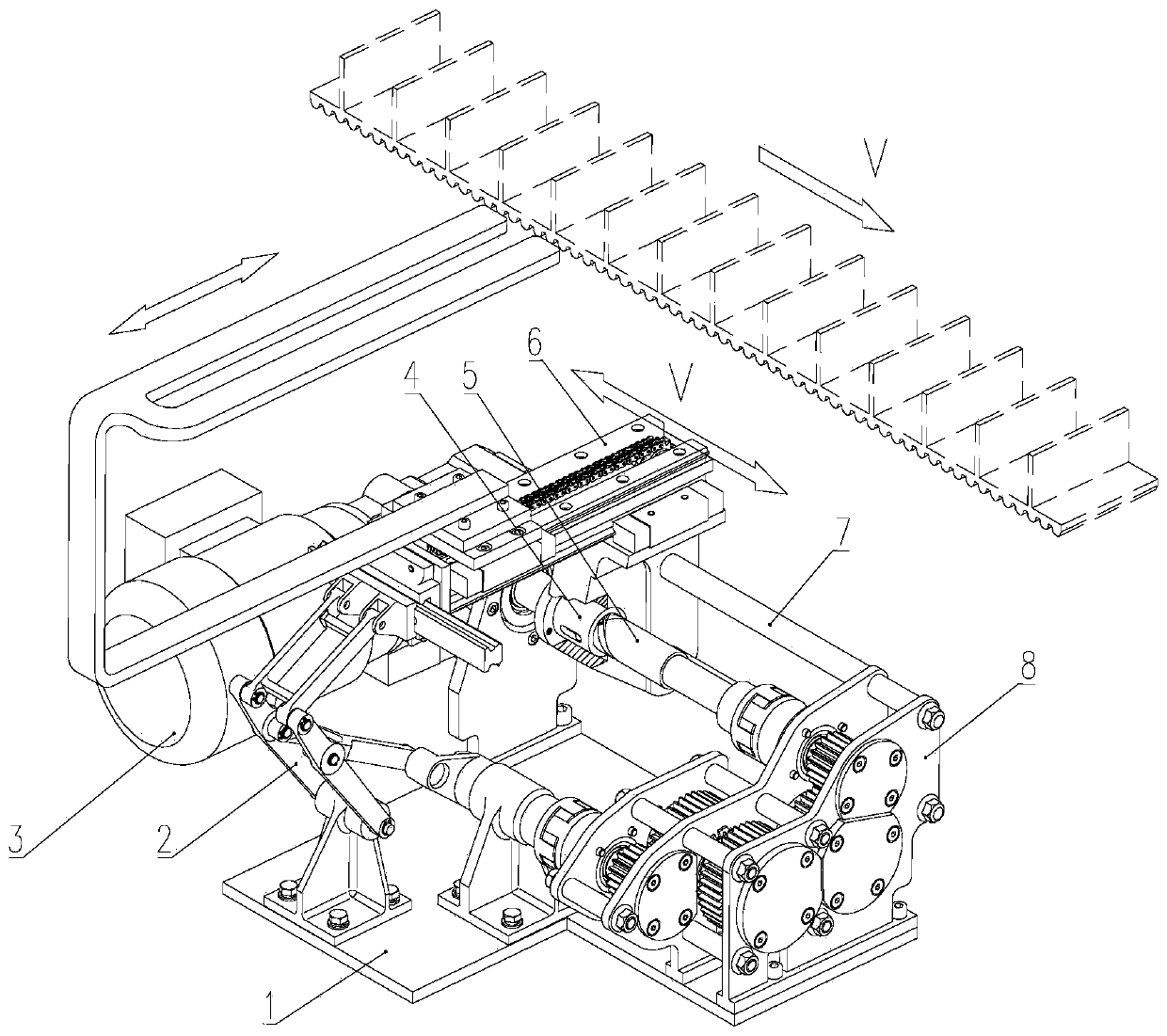
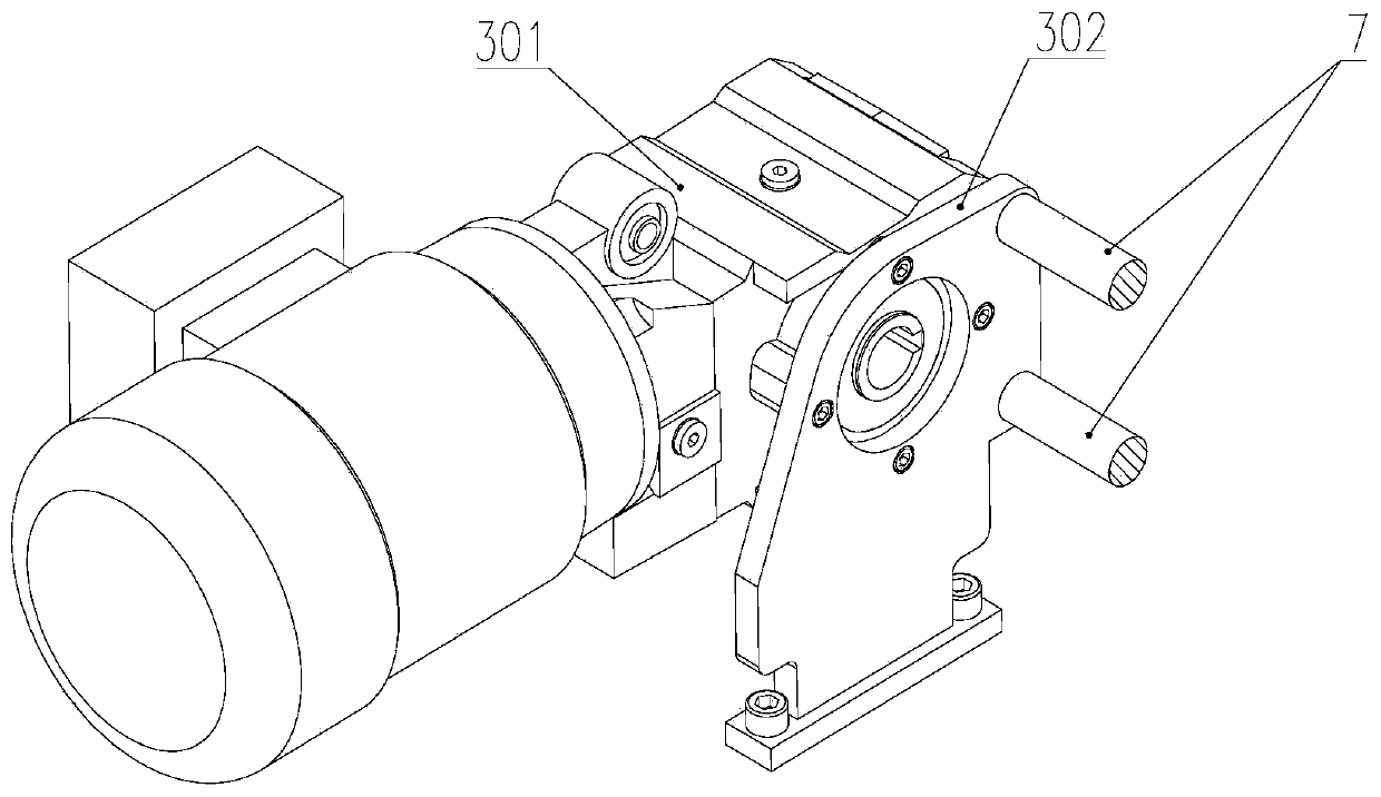
[0032] Such as figure 1As shown, it includes a base plate 1, a push-pull link assembly 2, a drive assembly 3, a screw sleeve 4, a reciprocating screw 5, a push head assembly 6, two connecting guide rods 7 and an intermittent output reduction box 8, and the drive assembly 3 is installed on the base plate 1 The intermittent output reduction box 8 is installed on the other side of the base plate 1, the drive assembly 3 and the intermittent output reduction box 8 are connected by two connecting guide rods 7 at fixed distances, and the push head assembly 6 slides with the two connecting guide rods 7 connection, the screw sleeve 4 is fixed at the lower part of the push head assembly 6, and the reciprocating screw 5 is threaded through the screw sleeve 4 to form a screw transmission connection, such as image 3 As shown, the output end of t...


PUM


Abstract

The invention discloses a continuous reciprocating type pushing device. A driving assembly is mounted on a substrate, and an intermittent output gearbox is mounted on the substrate. The driving assembly and the intermittent output gearbox are in fixed-distance connection through two connecting guide rods, and a pushing head assembly is in sliding connection with the two connecting guide rods. A screw rod sleeve is fixed to the lower portion of the pushing head assembly. A reciprocating screw rod penetrates through the screw rod sleeve to be sleeved with the screw rod sleeve to form spiral transmission connection. One end of the reciprocating screw rod stretches into a hollow output shaft of the driving assembly, and the reciprocating screw rod and the hollow output shaft are coaxially connected through a bond. The reciprocating screw rod and an input shaft of the intermittent output gearbox are in synchronous rotation connection through a coupler. A push-pull link assembly is fixed to the substrate. An output shaft of the intermittent output gearbox is connected to the side of the pushing head assembly through the push-pull link assembly. According to the continuous reciprocating type pushing device, a pushing head can synchronously and homodromously move along with a conveying belt in the transverse direction, the conveying belt does not need to stop, and the size of all link components is reduced; and the stability of the mechanism is improved, additional dynamic loads on the components are reduced, and the application range is wide.

Description

technical field [0001] The invention belongs to a material pushing device in a carton automatic packaging machine, in particular to a continuous reciprocating material pushing device. Background technique [0002] Nowadays, with the development of social productivity and the improvement of people's living standards, people's requirements for material living standards are also getting higher and higher. Correspondingly, a large number of various commodities are produced to meet market demand. It also gave birth to the development of the packaging machinery industry. Carton packaging machine is a kind of packaging equipment with a large proportion of automatic packaging machinery. It is mostly used in the food, pharmaceutical and cosmetic industries. Carton packaging machine generally includes suction box device, conveying device, pushing device, box sealing device and other parts. The pushing device is an important part of it. [0003] The pushing device of the traditional ...

Claims


Application Information

Patent Timeline
IPC IPC(8): B65B35/40B65B35/44
CPCB65B35/40B65B35/44
Inventor 娄海峰童俊华李振朱赢鹏
Owner ZHEJIANG SCI-TECH UNIV
Features
  • R&D
  • Intellectual Property
  • Life Sciences
  • Materials
  • Tech Scout
  • Unparalleled Data Quality
  • Higher Quality Content
  • 60% Fewer Hallucinations
Learn More