Anchor node position obtaining method for underwater optical communication network

An optical communication network and acquisition method technology, applied in the field of anchor node position acquisition of underwater optical communication network, can solve problems such as anchor node drift, influence network performance, communication link failure, etc., to reduce influence and achieve good communication effect Effect

Active Publication Date: 2019-09-27
HUAZHONG UNIV OF SCI & TECH
View PDF5 Cites 0 Cited by
  • Summary
  • Abstract
  • Description
  • Claims
  • Application Information

AI Technical Summary

Problems solved by technology

[0004] However, underwater optical communication usually requires the alignment of the communication link, but the drift of the anchor node is often caused by the movement of the water flow underwater, which eventually leads to the failure of the communication link and seriously affects the performance of the network. In order to reduce the impact of the water flow on the underwater The influence of optical communication network performance, it is necessary to study the movement of anchor nodes under the action of water flow
[0005] At present, although there are many underwater mobile models, they are all aimed at underwater acoustic networks, and the nodes are free to move with the water flow without any constraints; in terms of water-optical communication, most of the research is on channel models and optical signal modulation, etc., almost The effect of water flow on the movement of anchor nodes was not studied

Method used


Image

  • Anchor node position obtaining method for underwater optical communication network
  • Anchor node position obtaining method for underwater optical communication network
  • Anchor node position obtaining method for underwater optical communication network

Examples


Embodiment Construction

[0033] In order to make the object, technical solution and advantages of the present invention clearer, the present invention will be further described in detail below in conjunction with the accompanying drawings and embodiments. It should be understood that the specific embodiments described here are only used to explain the present invention, not to limit the present invention.

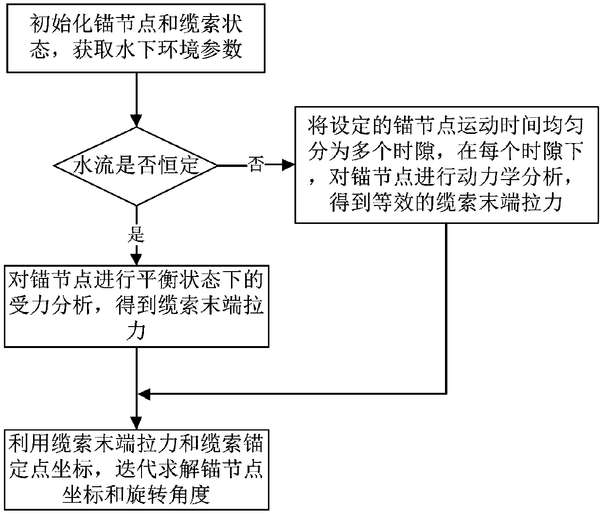
[0034] refer to figure 1 , a method for acquiring the position of an anchor node of an underwater optical communication network provided by the present invention, comprising:

[0035] (1) Initialize the status of the cables and anchor nodes in the underwater optical communication network, enable the anchor nodes to perform alignment communication, and obtain underwater environment parameters;

[0036] Specifically, the anchor node in the present invention refers to an underwater optical communication device anchored by a cable, which is a spherical structure. Initialize the state of the cable and...


PUM


Abstract

The invention discloses an anchor node position acquisition method for an underwater optical communication network, which comprises the following steps: initializing states of a cable rope and an anchor node in the underwater optical communication network, enabling the anchor node to perform aligned communication, and acquiring underwater environment parameters; when the water flow speed is constant, conducting stress analysis in a balanced state on the anchor nodes, and obtaining the pulling force at the tail end of the cable; when the water flow speed is not constant, dividing the set anchor node movement time evenly into a plurality of time slots, and under each time slot, conducting dynamic analysis on the anchor nodes to obtain equivalent cable tail end pulling force; and iteratively solving an anchor node coordinate and a rotation angle by utilizing the cable tail end pulling force and the cable anchor point coordinate. According to the method, the moving position of the anchor node can be accurately obtained in the water flow, the influence of the movement of the anchor node on the received light intensity is analyzed, more reasonable communication parameters and deployment schemes are designed, the influence of the water flow on the network communication performance is reduced, and even the water flow is utilized to a certain extent to achieve a better communication effect.

Description

technical field [0001] The invention belongs to the field of underwater optical communication, and more particularly relates to a method for acquiring the position of an anchor node of an underwater optical communication network. Background technique [0002] Underwater wireless sensor network has a wide range of applications in pollution monitoring, marine data collection, auxiliary navigation and national defense security, but it also faces many challenges due to the complex underwater environment. [0003] Underwater acoustic sensing technology is a communication technology that has been extensively studied and used in underwater environments. A large number of experimental results and practical experience show that the speed of underwater acoustic communication is slow and the delay is high. Compared with electromagnetic wave communication on land, the speed is several orders of magnitude lower, which seriously affects the real-time performance of communication; The typ...

Claims


Application Information

Patent Timeline
Patent Type & Authority Applications(China)
IPC IPC(8): H04B13/02H04B10/11G01D21/02
CPCG01D21/02H04B10/11H04B13/02
Inventor 胡晓娅许力
Owner HUAZHONG UNIV OF SCI & TECH
Why Eureka
Try Eureka