
External fixing frame with adjustable stress

An external fixator, adjustable technology, applied in the field of medical devices, can solve the problems of femoral head stress, wear, unfavorable femoral head shaping, etc., to achieve the effect of preventing excessive force and firm fixation

Pending Publication Date: 2019-10-01
丁浩男
View PDF5 Cites 1 Cited by
  • Summary
  • Abstract
  • Description
  • Claims
  • Application Information

AI Technical Summary

Problems solved by technology

When the external fixator is fixed at the hip joint, it is not conducive to the shaping of the femoral head, and the femoral head is under stress, which will cause excessive stress and wear on the femoral head

Method used


Image

  • External fixing frame with adjustable stress
  • External fixing frame with adjustable stress
  • External fixing frame with adjustable stress

Examples


Embodiment example 1

[0030] (1) Make the circle center of the rotating rod connecting screw hole of the rotating rod connecting block of the main fixture align with the patient's acetabular fossa;

[0031] (2) The main fixing frame and the auxiliary fixing frame are connected by screws, and the upper fixing screw position and the fixing screw position are inserted into fixing nails;

[0032] (3) The fixation screws at the upper fixation screw position and the upper fixation screw position at the upper and middle parts are placed above the unoperated hip bone;

[0033] (4) The fixation nails located at the lower fixation screw position and the lower upper fixation screw position are placed in the surgically adjusted position of the affected part of the hip bone;

[0034] (5) The fixing screw position is tightened by screws and nuts to fix the position of the fixing nail;

[0035] (6) The rotating rod is connected with the upper fixing frame, and the rotating rod is fixed by screws and nuts;

[00...

Embodiment example 2

[0040] (1) Make the circle center of the rotating rod connecting screw hole of the rotating rod connecting block of the main fixture align with the patient's acetabular fossa;

[0041] (2) The main fixing frame and the auxiliary fixing frame are connected by screws, and the upper fixing screw position and the fixing screw position are inserted into fixing nails;

[0042] (3) The fixation screws at the upper fixation screw position and the upper fixation screw position at the upper and middle parts are placed in the surgically adjusted position of the affected part of the hip bone;

[0043] (4) The fixation nails located at the lower fixation screw position and the lower upper fixation screw position are placed below the affected part of the unoperated hip bone;

[0044] (5) The fixing screw position is tightened by screws and nuts to fix the position of the fixing nail;

[0045] (6) The rotating rod is connected with the upper fixing frame, and the rotating rod is fixed by sc...


PUM


Abstract

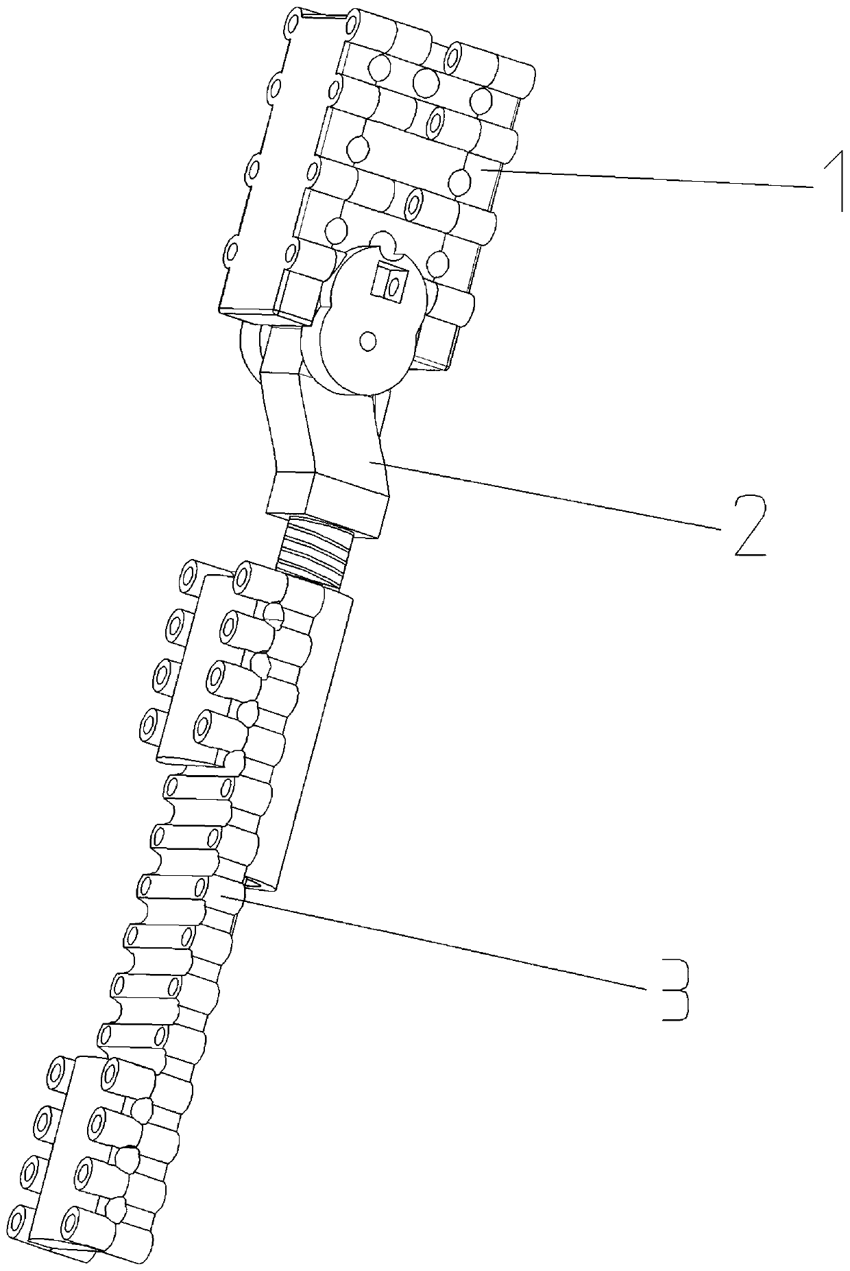
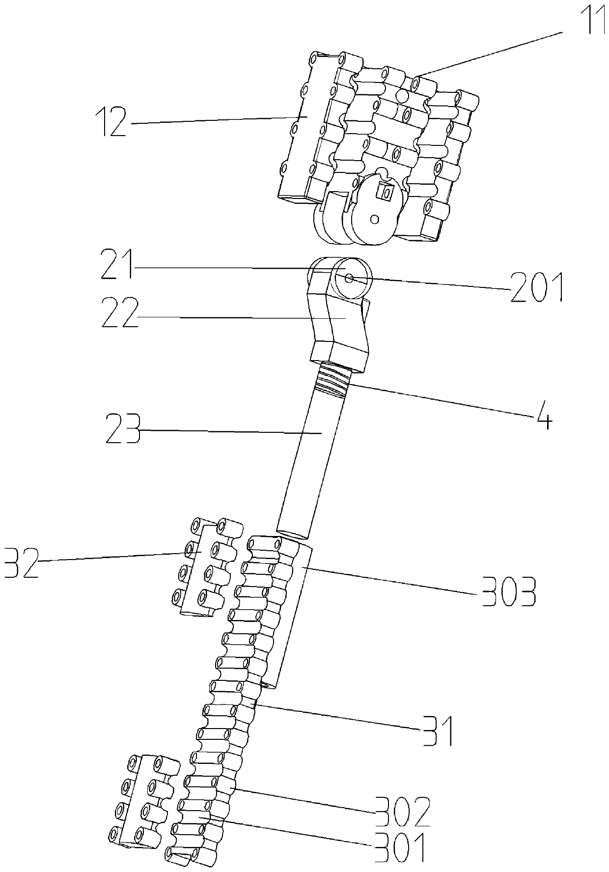
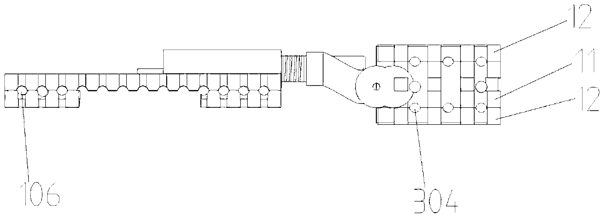
The invention provides an external fixing frame with adjustable stress. The external fixing frame comprises an upper fixing frame body, a rotary rod and a lower fixing frame body, the upper fixing frame body comprises a main fixing frame body and auxiliary fixing frame bodies, and half-cylinder grooves of the main fixing frame body and the auxiliary fixing frame bodies form upper fixing screw positions; the rotary rod comprises a rotary cylinder, a connection fixed platform and a connection rod, half-cylinder grooves of a main frame body and a locating frame body form lower fixing screw positions, and the lower fixing frame body comprises the main frame body and the locating frame body; the upper fixing frame body is connected with the rotary rod, the connection rod of the rotary rod is placed in a sleeve of the lower locating frame body; a plurality of fixing screw positions are arranged, fixation is firm, the external fixing frame can rotate with joint motion, and a spring is arranged between the rotary rod and the lower fixing frame body; the stress applied to caput femoris in acetabulum can be adjusted during motion, and abnormal stress applied to the caput femoris in the acetabulum and abrasion and deformation of the caput femoris are avoided.

Description

technical field [0001] The invention relates to the technical field of medical devices, in particular to a stress-adjustable external fixator. Background technique [0002] At present, intramedullary nails are generally used for internal fixation after orthopedic surgery shelf Cooperate with the external fixator of the external fixator for treatment, but the use of the internal fixation method is limited, and it is easy to damage the endosteal blood supply and affect the cortical bone. In order to achieve the effect of local fixation, the existing external fixator spans The frame of the joint cannot move. [0003] The hip joint is composed of the hip bone and the femur. Many hip joint diseases such as dysplasia, trauma, infection, or tumor require surgical treatment. After hip surgery, the femur is generally required to fix the surgical site. The fixation range spans The hip joint, as a walking joint, requires functional exercise during fixation after surgical treatment, b...

Claims


Application Information

Patent Timeline
IPC IPC(8): A61B17/60
CPCA61B17/60
Inventor 丁焕文
Owner 丁浩男
Learn More