Automobile chassis punching die

A technology for stamping dies and automobile chassis, which is applied in the field of stamping dies, can solve problems such as low operation efficiency, difficulty in adjusting the level and height of the die, and achieve the effects of convenient inspection and maintenance, overcoming the complexity of mechanical parts, and excellent applicability

Active Publication Date: 2019-10-01
ZHIJIA TOOL & DIE
View PDF5 Cites 1 Cited by
  • Summary
  • Abstract
  • Description
  • Claims
  • Application Information

AI Technical Summary

Problems solved by technology

[0005] The purpose of the present invention is to provide a stamping die for automobile chassis to solve the technical problems in the prior art that the level and height of the die are difficult to adjust and the operation efficiency is low

Method used


Image

  • Automobile chassis punching die
  • Automobile chassis punching die
  • Automobile chassis punching die

Examples


Embodiment Construction

[0037] The present invention is described in detail below in conjunction with accompanying drawing:

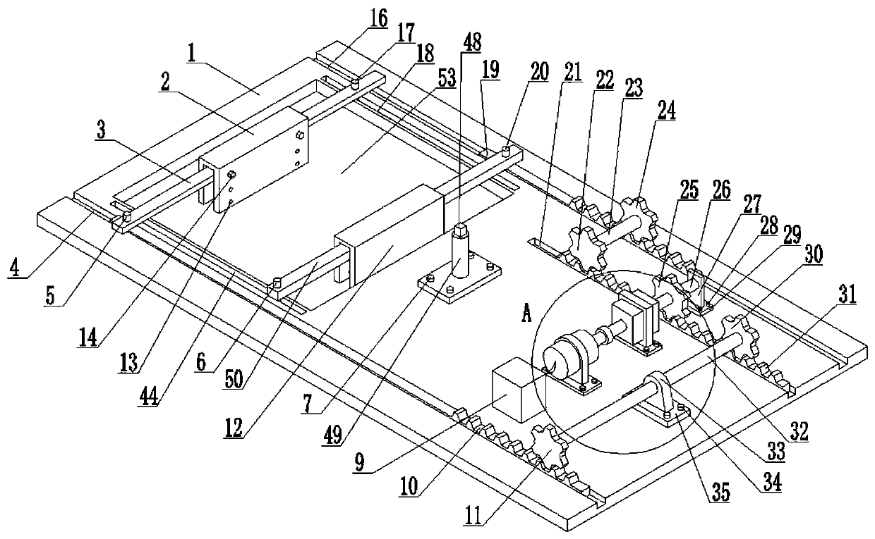
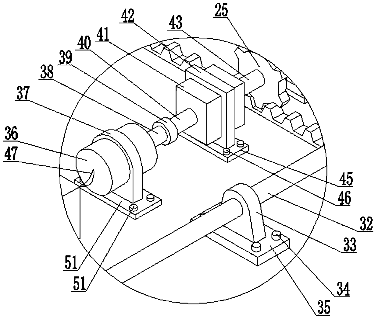
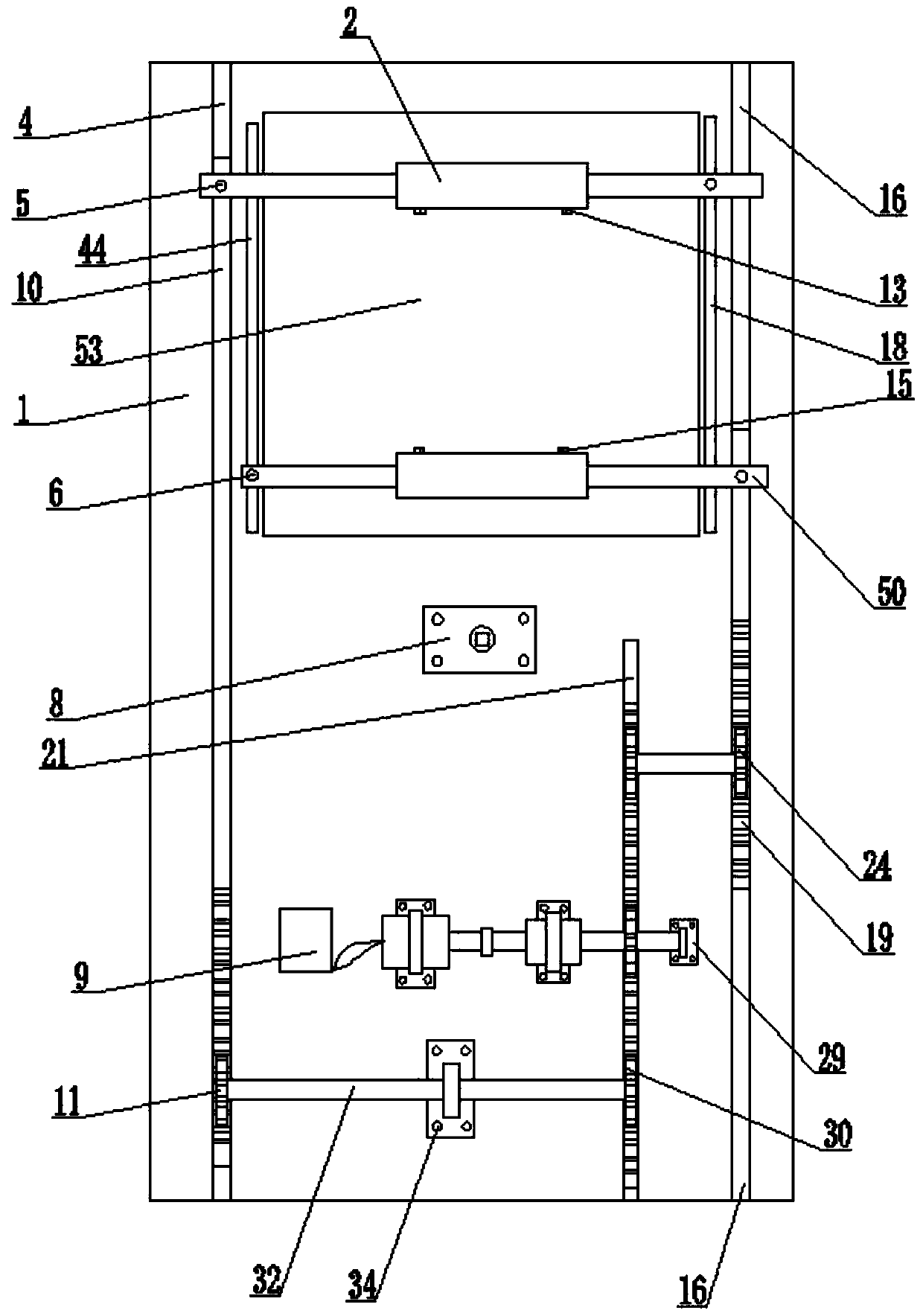
[0038] refer to Figure 1 to Figure 5A stamping die for an automobile chassis provided by the present invention includes a base plate 1, a first sliding support rod 3, a second sliding support rod 50, a motor 36, and a reducer 41. The base plate 1 is provided with a first bottom plate 8, The second base plate 29, the third base plate 35, the fourth base plate 45 and the fifth base plate 51, the top of the first sliding support bar 3 is provided with the first mold 2, the left and right sides of the first sliding support bar 3 The sides are respectively fixed with the first left sliding column 5 and the first right sliding column 17, the bottom of the first right sliding column 17 is in contact with the first right chute 18 and can follow the first right chute 18 The length direction moves linearly; the top of the second sliding support bar 50 is provided with a second mold 12...


PUM


Abstract

The invention discloses an automobile chassis punching die. The automobile chassis punching die comprises a base plate (1), a first sliding supporting rod (3), a second sliding supporting rod (50), amotor (36) and a speed reducer (41), wherein a first bottom plate (8), a second bottom plate (29), a third bottom plate (35), a fourth bottom plate (45) and a fifth bottom plate (51) are arranged on the base plate (1); a first die (2) is arranged on the top part of the first sliding supporting rod (3); a first left sliding column (5) and a first right sliding column (17) are correspondingly fixedly arranged at the left side and the right side of the first sliding supporting rod (3); the bottom part of the first right sliding column (17) is in contact with a first right chute (18) and can linearly move in the length direction of the first right chute (18); a second die (12) is arranged on the top part of the second sliding supporting rod (50); a second left sliding column (6) and a second right sliding column (20) are correspondingly fixedly arranged at the left side and the right side of the second sliding supporting rod (50); and the bottom part of the second left sliding column (6) is in contact with a second left chute (44) and can linearly move in the length direction of the second left chute (44). According to the automobile chassis punching die, the abovementioned devise arecombined to flexibly control the positions of the first die (2) and the second die (12), so that the implementing cost is decreased while the popularization and application are conveniently carried out.

Description

technical field [0001] The invention relates to the field of stamping dies, in particular to an automobile chassis stamping die. Background technique [0002] Auto stampings are metal stampings that make up auto parts. Among automobile stamping parts, some parts become auto parts directly after stamping, and the other parts need to be welded, machined, or painted before they can become auto parts after stamping. The automobile chassis stamping parts are generally large-scale products, which require a large-tonnage press and can only be realized by two-person operation. The structure is complex, there are many assembly holes, and there are many varieties. The hole position is strictly required. [0003] Based on the above, when stamping the existing automobile chassis, usually a set of dies can only be used to punch out one flat hole, and many product assembly holes of the chassis parts are located on different surfaces or have angles, so it is impossible to stamp the same p...

Claims


Application Information

Patent Timeline
Patent Type & Authority Applications(China)
IPC IPC(8): B21D37/10B21D37/04B21D53/88
CPCB21D37/04B21D37/10B21D53/88
Inventor 不公告发明人
Owner ZHIJIA TOOL & DIE
Why Eureka
Try Eureka