Body roll driving mechanism and vehicle applying same

A driving mechanism and body technology, applied in the direction of body, steering mechanism, body stability, etc., can solve the problems of poor ride comfort, safety and reliability, complex structure, high cost, etc., to eliminate transmission gap, improve stability and reliability, maintain The effect of driving posture

Active Publication Date: 2019-10-01
河南坐骑科技有限公司
View PDF8 Cites 10 Cited by
  • Summary
  • Abstract
  • Description
  • Claims
  • Application Information

AI Technical Summary

Problems solved by technology

[0003] Vehicle active roll technology is usually implemented in two ways: independent body roll and body and wheel linkage roll, among which: body and wheel linkage roll, the interaction between body roll and vehicle steering motion, and the steering stability of the vehicle when turning , ride comfort and safety are better, and it is necessary to adopt two-wheel independent steering or four-wheel independent steering, or use a vehicle steering and rolling linkage device composed of a rolling mechanism and a steering mechanism, but the structure is complicated and the cost is high, so it is suitable for High-end vehicles: independent body roll mode, body roll and vehicle steering movement are carried out independently without interfering with each other, any steering mechanism can be used, the structure is simple, and the cost is low. Usually, the actuator directly drives the body to rotate relative to the frame, resulting in The handling stability, ride comfort and safety reliability of the vehicle are poor when turning; explore the drive mode of independent body roll, and study the drive and control method of independent body roll, in order to reduce the cost of active roll vehicles and improve the performance of independent body roll vehicles It has theoretical significance and practical value

Method used


Image

  • Body roll driving mechanism and vehicle applying same
  • Body roll driving mechanism and vehicle applying same
  • Body roll driving mechanism and vehicle applying same

Examples


Embodiment Construction

[0016] Embodiments of the present invention will be described below according to the accompanying drawings.

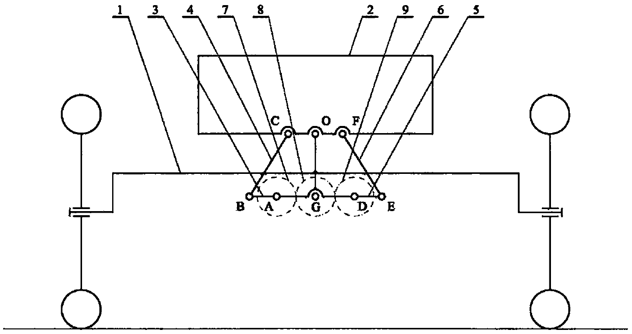
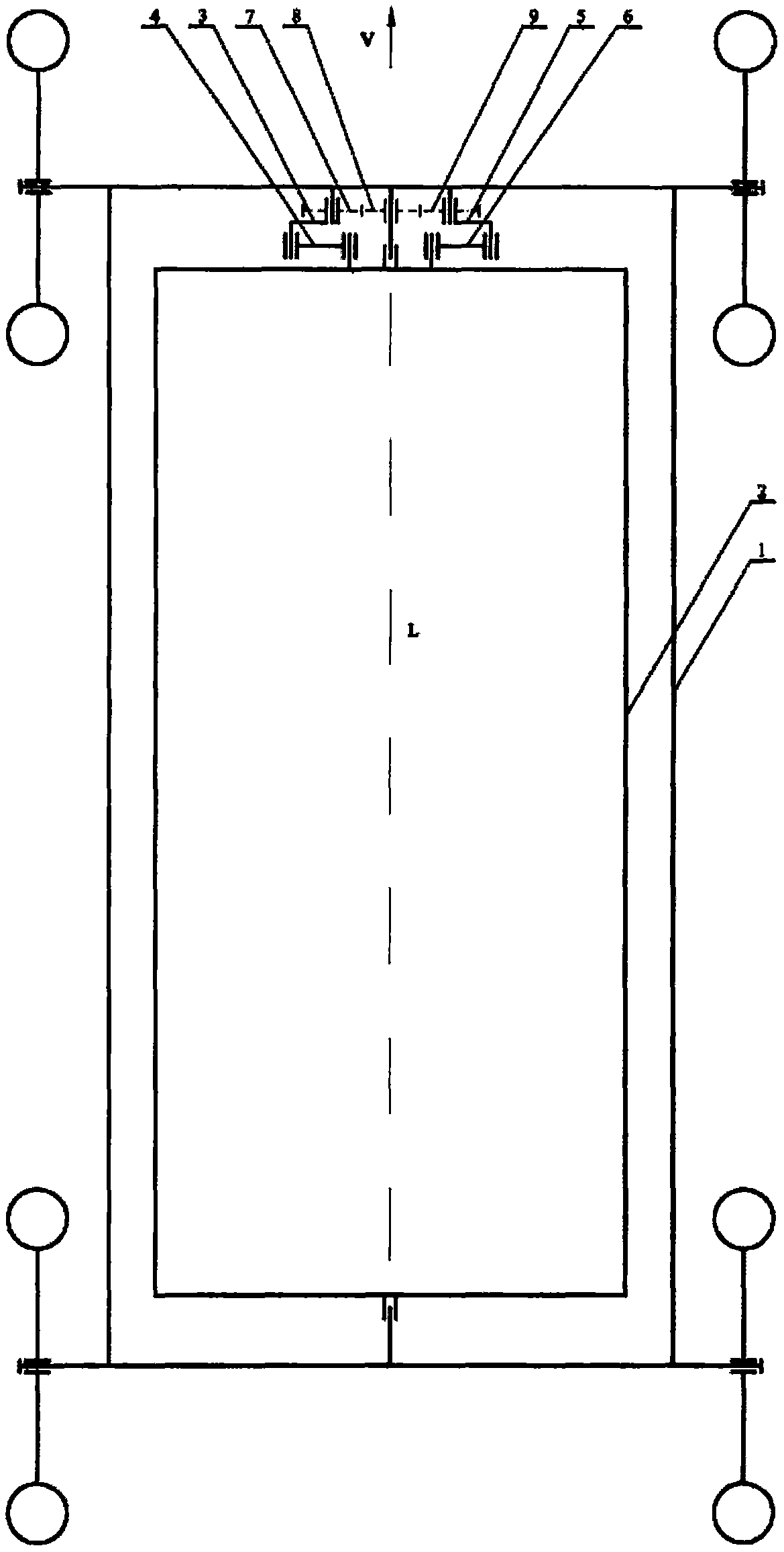
[0017] figure 1 The schematic diagram of the body roll driving mechanism is shown, the body roll driving mechanism includes: frame (1), body (2), left crank (3), left connecting rod (4), right crank (5), right connecting rod Rod (6), left gear (7), middle gear (8), right gear (9), vehicle body (2) and vehicle frame (1) rotate around the roll axis L at point O, and the roll center O is located at the On the centerline of the frame (1) and the symmetrical line of the vehicle body (2), one end of the left crank (3) is rotationally connected with the vehicle frame (1) at point A, and one end of the left connecting rod (4) is rotationally connected with the vehicle body (2) at point C , the other end of the left crank (3) is rotationally connected with the other end of the left connecting rod (4), at connection point B, one end of the right crank (5) is rotationally connec...


PUM


Abstract

The invention relates to the technical field of vehicle chassis and discloses a body roll driving mechanism and a vehicle applying the same. The body roll driving mechanism comprises a frame, a body,a left crankshaft, a left connecting rod, a right crankshaft, a right connecting rod, a left gear, a middle gear and a right gear. The body and the frame are rotatably connected around roll axis, theleft crankshaft, the left connecting rod and the right connecting rod form two moving chains connecting the body and the frame, the left, middle and right gears are in engaged transmission, the left gear, the left crankshaft, the right gear and the right crankshaft rotate at equal angles in a same direction, an actuator drives the middle gear to rotate, the body is driven by the double serial moving chains to roll, a closed transmission loop eliminates a transmission gap and reduces moving impact, so that the stability and reliability of a vehicle in the roll process are improved. When the body roll driving mechanism is applied to the vehicle turning or travelling on an inclined pavement, the body inclines a certain angle actively to resist the centrifugal force or the rollover force, so that a stable driving gesture of the vehicle is kept.

Description

technical field [0001] The invention relates to a vehicle body roll driving mechanism and a vehicle using the same, belonging to the technical field of vehicle chassis, in particular to the technical field of vehicle body roll driving and control. Background technique [0002] The active roll control system improves the handling stability, smoothness, traffic speed and safety of the vehicle when turning by controlling the degree of inclination of the vehicle to the inner side of the turn. When crossing an inclined road, it automatically tilts at a certain angle to generate a balance moment to resist the centrifugal force or rollover force on the vehicle, so as to maintain a stable driving posture of the vehicle. [0003] Vehicle active roll technology is usually implemented in two ways: independent body roll and body and wheel linkage roll, among which: body and wheel linkage roll, the interaction between body roll and vehicle steering motion, and the steering stability of t...

Claims


Application Information

Patent Timeline
Patent Type & Authority Applications(China)
IPC IPC(8): B62D37/00B62D9/02
CPCB62D9/02B62D37/00
Inventor 王亚魏文军
Owner 河南坐骑科技有限公司
Why Eureka
Try Eureka