
Tethered unmanned aerial vehicle system without airborne high-power power supply

A high-power power supply and unmanned aerial vehicle technology, which is applied to ground devices for tethered aircraft, unmanned aerial vehicles, motor vehicles, etc., can solve problems such as intractability, property damage, and high on-board power supply, etc. Achieve the effect of reducing weight, simplifying system composition, and reducing power conversion links

Inactive Publication Date: 2019-10-01
深圳市科卫泰实业发展有限公司
View PDF9 Cites 1 Cited by
  • Summary
  • Abstract
  • Description
  • Claims
  • Application Information

AI Technical Summary

Problems solved by technology

The 15kw airborne power supply weighs more than 10Kg, which greatly affects the load capacity of the drone
[0004] On the other hand, the reliability requirements of the airborne DC / DC power supply module are very high. Once the airborne power supply module fails, the UAV crashes, causing property loss and personal injury.
[0005] On the other hand, the conversion efficiency of the onboard power supply system is about 90%, and the conversion efficiency of the onboard power supply reduces the energy utilization rate of the system
[0006] On the other hand, due to the large power and strict weight requirements of the airborne power supply, EMC is very difficult to handle. The weight brought by the external EMC components has the disadvantage that the load capacity of the tethered UAV system cannot be increased.

Method used


Image

  • Tethered unmanned aerial vehicle system without airborne high-power power supply
  • Tethered unmanned aerial vehicle system without airborne high-power power supply
  • Tethered unmanned aerial vehicle system without airborne high-power power supply

Examples


Embodiment Construction

[0023] The following will clearly and completely describe the technical solutions in the embodiments of the present invention with reference to the accompanying drawings in the embodiments of the present invention. Obviously, the described embodiments are only some, not all, embodiments of the present invention. Based on the embodiments of the present invention, all other embodiments obtained by persons of ordinary skill in the art without making creative efforts belong to the protection scope of the present invention.

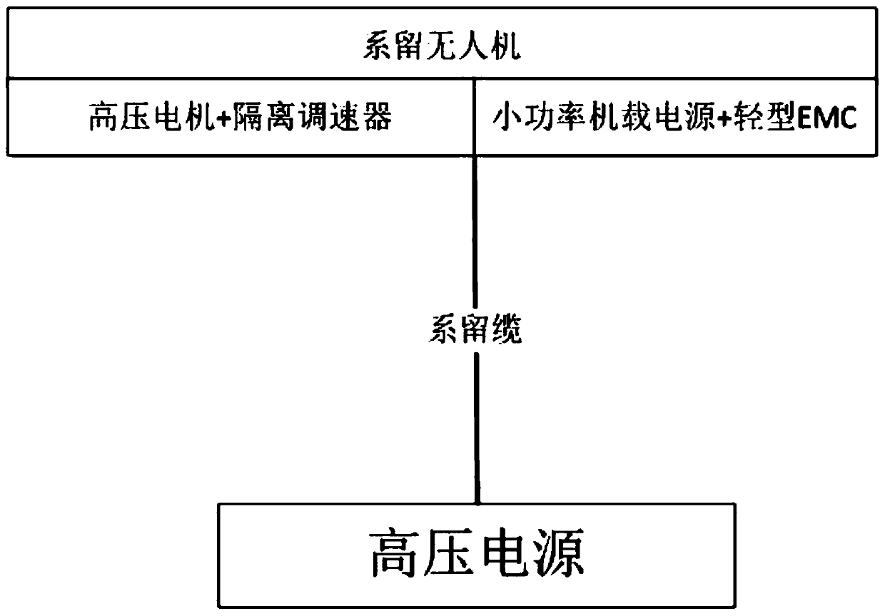
[0024] see Figure 1-4 , the present invention provides a technical solution: a tethered drone system without onboard high-power power supply, including a tethered drone and a high-voltage power supply, and the tethered drone includes a high-voltage motor and an isolated governor , the tethered drone also includes a low-power onboard power supply and a light EMC, and the tethered drone is connected to a high-voltage power supply through a tethered cable.

[0...


PUM


Abstract

The invention discloses a tethered unmanned aerial vehicle system without an airborne high-power power supply. The system comprises a tethered unmanned aerial vehicle and a high voltage power supply.The tethered unmanned aerial vehicle comprises a high voltage motor and an isolating speed regulator. The tethered unmanned aerial vehicle also comprises a small power airborne power supply and a light EMC. The tethered unmanned aerial vehicle is connected to the high voltage power supply through a tethering cable. The airborne power supply is cancelled at a man-machine end, so that the flying weight is reduced, and the unmanned aerial vehicle can carry a higher load. Negative effects caused by reliability of the airborne power supply, conversion efficiency, heat dissipation and the like are excluded, so that the system composition is simplified. The unmanned aerial vehicle end only needs to remain a small power high voltage and low voltage conversion module, so that control parts of the system are powered. The electric energy conversion link is cancelled, and an electronic speed regulator of the high voltage motor is researched, so that speed regulating control on the high voltage motor is achieved. Common mode and difference mode filter circuits are added to the EMC in a small current mode, so that the weight of the filter circuit can be alleviated by over 90%. A magnetic core and a conductor can be light in weight.

Description

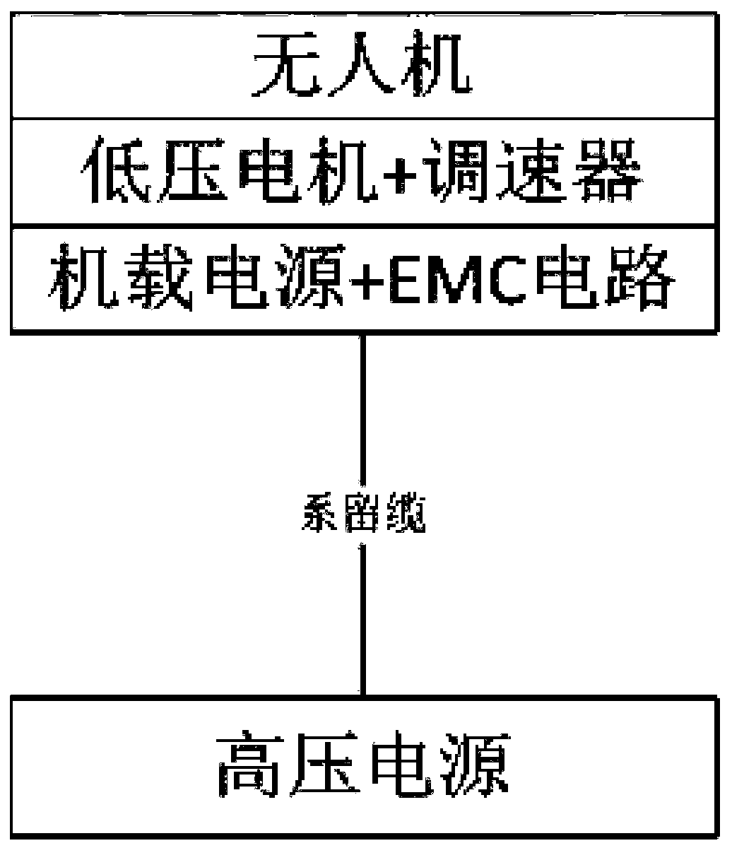
technical field [0001] The invention relates to the technical field of tethered drones, in particular to a tethered drone system without onboard high-power power supply. Background technique [0002] The tethered UAV system is a system that uses ground power supply and an onboard high-power power supply to complete high-voltage conversion to low-voltage. In order to reduce the line loss, the usual method is to convert the ground AC220V or AC380V input to DC400-DC1000V or above voltage, which is transmitted to the drone’s airborne terminal through a tethered cable, and the transmission distance can reach 100 meters to 300 meters. The UAV is equipped with an airborne high-power power module, usually the power of the power module is between 3KW and 20KW, and the input voltage of the power module is the output voltage of the ground terminal, usually DC300-DC1000V. The output voltage of the onboard high-power power supply is 6s / 12s (25.2V, 50.4V). The output low voltage is dire...

Claims


Application Information

Patent Timeline
Patent Type & Authority Applications(China)
IPC IPC(8): B64F3/02B64D27/24
CPCB64F3/02B64D27/24B64U50/19
Inventor 宋文刚范桐桐丁红亮寇崇晓朱琪
Owner 深圳市科卫泰实业发展有限公司
Learn More