Aerospace high-power lamp

A high-power, lamp technology, applied in the field of optical lighting, can solve problems such as inability to directly apply and difficult to control the heat of lamps, and achieve the effect of ensuring thermal conductivity

Pending Publication Date: 2019-10-01
XI'AN INST OF OPTICS & FINE MECHANICS - CHINESE ACAD OF SCI
View PDF5 Cites 0 Cited by
  • Summary
  • Abstract
  • Description
  • Claims
  • Application Information

AI Technical Summary

Problems solved by technology

[0003] Although there are many existing high-power lamps, they cannot be directly applied in aerospace
The main problem is that the impact and vibration of the rocket launcher on the luminaire is far greater than the requirements for general use on the ground. In addition, the light-emitting surface of the luminaire in space must be exposed to the outside, and it directly withstands the extremely high and low temperature environment in the sun and shadow areas. The luminaire itself The heat generated is also difficult to control

Method used


Image

  • Aerospace high-power lamp
  • Aerospace high-power lamp
  • Aerospace high-power lamp

Examples


Embodiment

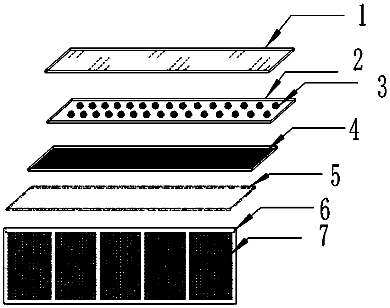
[0036] Such as figure 1 As shown, a high-power lamp for aerospace includes a protective window 1, a condenser lens 2, a lamp panel 3, a heat dissipation plate 4, a sealing strip 5, a housing 6, and a thermal buffer medium 7;

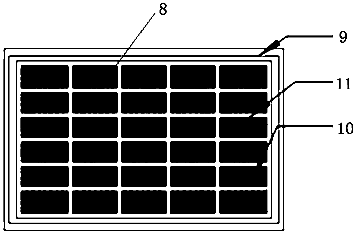
[0037] Wherein, the housing 6 is provided with a thermal buffer medium filling area 8, and the thermal buffer medium 7 is filled in the filling area 8; a sealing strip installation groove 9 is opened between the thermal buffer medium filling area 8 and the inner wall of the housing 6, and the sealing strip is sealed. The strip 5 is installed in the sealing strip installation groove 9; the heat dissipation plate 4 is arranged above the filling area 8, and is closely attached to the heat buffer medium 7; the LED lamp board 3 is installed above the heat dissipation plate 4, and the LED A condenser lens 2 is installed on each LED lamp in the lamp panel 3 ; a protective window 1 is installed on the top of the housing 6 .

[0038] In this embodiment: the hous...


PUM


Abstract

The invention discloses an aerospace high-power lamp. The aerospace high-power lamp comprises a protective window, condensing lenses, an LED lamp panel, a thermal dissipating plate, a sealing strip, athermal buffer medium and a shell; a thermal buffer medium filling area is arranged in the shell and filled with the thermal buffer medium; a sealing strip mounting groove is formed between the thermal buffer medium filling area and the inner wall of the shell, and a sealing strip is mounted in the sealing strip mounting groove; the thermal dissipating plate is arranged above the filling area andis in close fit with the thermal buffer medium; the LED lamp panel is mounted on the upper part of the thermal dissipating plate, and the condensing lenses are mounted on all LED lamps in the LED lamp panel; and the protective window is mounted at the top of the shell. The thermal buffer medium is added on the aerospace high-power lamp, a close frame type structure is adopted, and thus it is ensured that the lamp meets the using requirements of high-power lighting under high and low temperature environments.

Description

technical field [0001] The invention belongs to the field of optical lighting, in particular to a high-power lamp for aerospace. Background technique [0002] Because of its high luminous efficiency, high-power lamps are widely used in the lighting of stadiums, exhibition centers, large shopping malls, industrial plants, street squares, stations, docks, ships and other large places. [0003] Although there are many existing high-power lamps, they cannot be directly applied in aerospace. The main problem is that the impact and vibration of the rocket launcher on the luminaire is far greater than the requirements for general use on the ground. In addition, the light-emitting surface of the luminaire in space must be exposed to the outside, and it directly withstands the extremely high and low temperature environment in the sun and shadow areas. The luminaire itself The heat generated is also difficult to control. Contents of the invention [0004] The purpose of the presen...

Claims


Application Information

Patent Timeline
Patent Type & Authority Applications(China)
IPC IPC(8): F21S8/00F21V5/04F21V7/24F21V25/00F21V29/70F21V29/85F21V31/00F28D20/02F21Y115/10
CPCF21S8/00F21V5/04F21V25/00F21V31/00F28D20/02F21V29/70F21V29/85F21Y2115/10F21V7/24Y02E60/14
Inventor 梅超史魁王华伟易波宋晓东
Owner XI'AN INST OF OPTICS & FINE MECHANICS - CHINESE ACAD OF SCI
Why Eureka
Try Eureka