Liquid distribution mechanism with uniform liquid distribution function, installation method thereof and air conditioning system

An installation method and liquid separation technology, which is applied in the direction of refrigerators, mechanical equipment, refrigeration and liquefaction, etc., can solve the problem that the liquid separation head cannot evenly distribute liquid, and achieve the effect of overcoming the large difference in the dryness of the refrigerant

Active Publication Date: 2019-10-01
GREE ELECTRIC APPLIANCES INC
View PDF20 Cites 1 Cited by
  • Summary
  • Abstract
  • Description
  • Claims
  • Application Information

AI Technical Summary

Problems solved by technology

[0003] In order to solve the technical problem that the existing liquid dispensing head cannot evenly distribute liquid under the condition of uneven distribution of the two phases of the fluid, a uniform liquid dispensing device

Method used


Image

  • Liquid distribution mechanism with uniform liquid distribution function, installation method thereof and air conditioning system
  • Liquid distribution mechanism with uniform liquid distribution function, installation method thereof and air conditioning system
  • Liquid distribution mechanism with uniform liquid distribution function, installation method thereof and air conditioning system

Examples


Embodiment

[0031] The process of comparing the dispensing effect of the liquid dispenser head a of the prior art with the liquid dispenser head b of the present application is as follows:

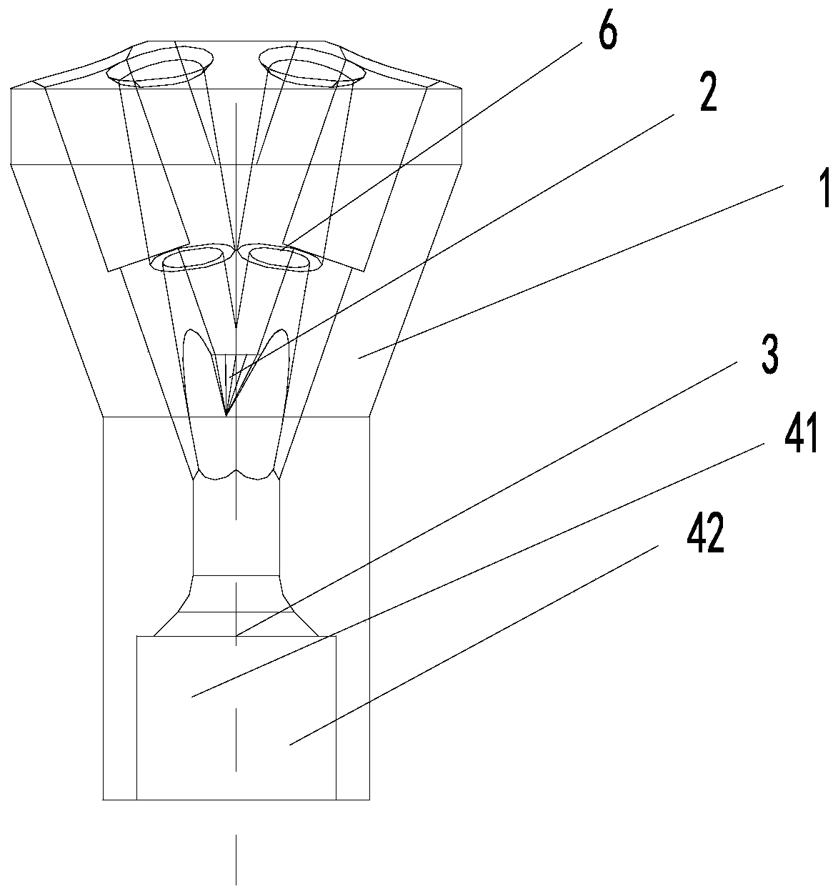
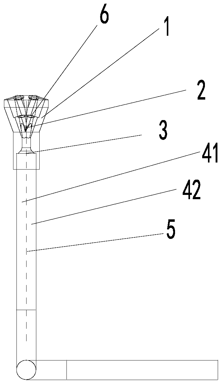
[0032] A liquid inlet pipe 5 with a 90° bend is connected to the liquid inlet 3 of the liquid dispenser head a and the liquid dispenser head b, wherein the apex of the split tip 2 of the liquid dispenser head 2 is moved away from the liquid inlet The direction of the liquid inlet direction of the tube 5 deviates by 0.7mm;

[0033] Keep the size of other parts, grid topology parameters and calculation process on the liquid head a and liquid head b completely consistent;

[0034] And set the inlet parameters of dispenser head a and dispenser head b as follows:

[0035] The dryness of the refrigerant inlet is 0.2; the inlet pressure is 1.15MPa; the inlet flow is 0.0528kg / s;

[0036] Finally, the results of Table 1 and Table 2 are obtained

[0037] Table 1 Distribution of refrigerant flow rate in each ...


PUM


Abstract

The invention provides a liquid distribution mechanism with a uniform liquid distribution function, an installation method thereof and an air conditioning system. The liquid distribution mechanism comprises a cylindrical body and a flow distribution pointed cone, wherein a liquid distribution cavity is formed in the cylindrical body, the flow distribution pointed cone is arranged in the liquid distribution cavity, and atop point of the flow distribution pointed cone is spaced from an axis of the cylindrical body. According to the liquid distribution mechanism with the uniform liquid distribution function, the installation method thereof and the air conditioning system provided by the invention, the distance between the top point of the flow distribution pointed cone and the axis of the cylindrical body is set, so that the top point of the flow distribution pointed cone points to a liquid phase concentration part, liquid phase refrigerant can uniformly enter a flow distribution hole under the flow guidance of the top point and a liquid distribution level, the problem that the refrigerant dryness in the flow distribution hole differs greatly due to uneven liquid distribution in theprior art is solved, and the purpose of uniform liquid distribution is achieved.

Description

technical field [0001] The invention relates to the technical field of fluid distributing devices, in particular to a liquid distributing mechanism with a uniform liquid dispensing function, an installation method thereof, and an air conditioning system. Background technique [0002] As an important part of the air-conditioning heat exchange system, the liquid distribution head, together with the capillary tube, is responsible for the distribution of the refrigerant flow in each branch before the system enters the heat exchanger. Whether the refrigerant flow distribution of each branch of the heat exchanger can be well matched with the wind speed distribution on the surface of the heat exchanger directly affects the heat transfer capacity of the air conditioning system; the conventional Venturi liquid separator design is usually based on the axisymmetric structure combination The principle of uniform liquid distribution is designed to pursue the maximum uniformity of liquid ...

Claims


Application Information

Patent Timeline
IPC IPC(8): F25B41/00F25B41/42
CPCF25B2500/09F25B41/40
Inventor 曾成马屈杨玉格叶剑夏凯
Owner GREE ELECTRIC APPLIANCES INC
Why Eureka
Try Eureka