
Electric spindle pneumatic loading device and state monitoring system

A technology of condition monitoring system and loading device, which is applied in the direction of measuring device, testing of mechanical parts, testing of machine/structural parts, etc., can solve problems such as high cost, time-consuming and laborious, and reduce timeliness of products, and achieve easy control, mechanical The effect of simple structure

Active Publication Date: 2019-10-01
TSINGHUA UNIV
View PDF7 Cites 5 Cited by
  • Summary
  • Abstract
  • Description
  • Claims
  • Application Information

AI Technical Summary

Problems solved by technology

At present, most domestic manufacturers of machine tools and parts use the method of tracking the usage of users to monitor the working conditions of machine tools. This method takes many years to record the fault information of machine tools, which is not only time-consuming and laborious, but also difficult to comprehensively Performance is accurately assessed and predicted
It can be seen that the conventional reliability test has defects such as long cycle, slow effect, large sample size, and high cost, which reduces the timeliness of products entering the market and affects the economic benefits of manufacturers.

Method used


Image

  • Electric spindle pneumatic loading device and state monitoring system
  • Electric spindle pneumatic loading device and state monitoring system
  • Electric spindle pneumatic loading device and state monitoring system

Examples


Embodiment Construction

[0029] The following describes in detail the embodiments of the present invention, examples of which are illustrated in the accompanying drawings, wherein the same or similar reference numerals refer to the same or similar elements or elements having the same or similar functions throughout. The embodiments described below with reference to the accompanying drawings are exemplary, and are intended to explain the present invention and should not be construed as limiting the present invention.

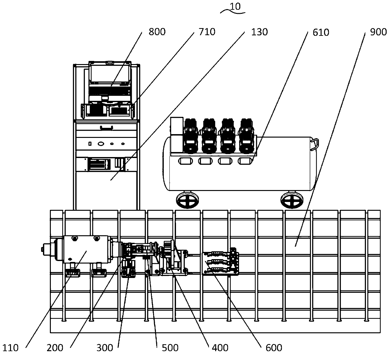
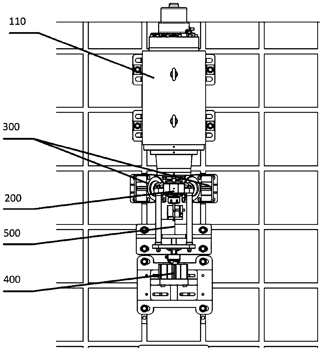
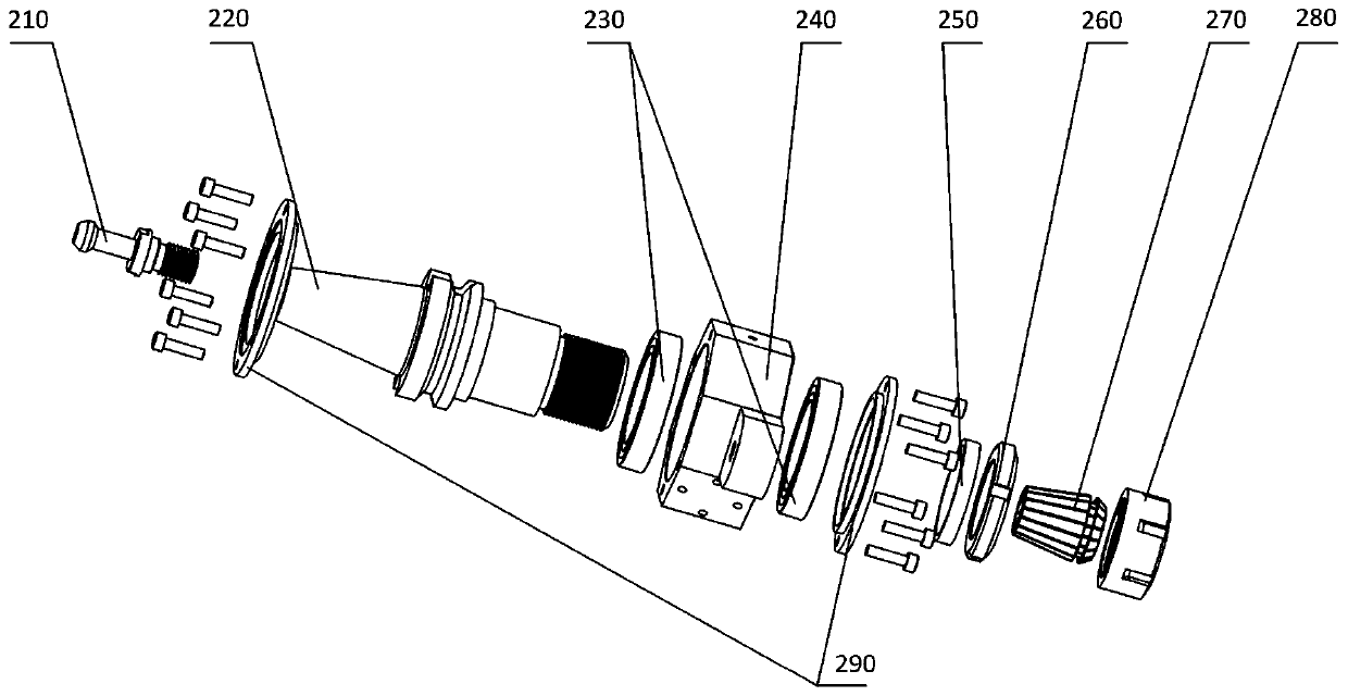
[0030] The following describes the electric spindle pneumatic loading device and the state monitoring system according to the embodiments of the present invention with reference to the accompanying drawings.

[0031] figure 1 It is a schematic structural diagram of an electric spindle pneumatic loading device and a state monitoring system according to an embodiment of the present invention.

[0032] like figure 1 As shown, the electro-spindle pneumatic loading device and state monitori...


PUM


Abstract

The invention discloses an electric spindle pneumatic loading device and state monitoring system. The electric spindle pneumatic loading device and state monitoring system comprises an electric spindle and control device, a bearing device, a radial force loading device, an axial force loading device, a spindle rotation precision monitoring device, a pneumatic control device, an NI signal acquisition system and an upper computer control device. According to the system, through pneumatic loading, a spindle loading mechanism is simple and compact in mechanical structure and easy to control, and an applied load is relatively large; radial force loading of any angle can be realized through synthesis of a radial force; various operation state information of the spindle, such as the rotation precision of the spindle, vibration and temperature signals of all parts of the spindle, current and speed signals of the spindle, an applied load force feedback signal and the like can be detected; and the system can be applied to the reliability loading research of the electric spindle of a machining center, so that the purposes of simulating actual working conditions of the spindle, monitoring theperformance and state of the spindle, and finally evaluating the reliability of the spindle are achieved.

Description

technical field [0001] The invention relates to the technical field of machine tool reliability testing, in particular to an electric spindle pneumatic loading device and a state monitoring system. Background technique [0002] Electric spindle is one of the core components of CNC machine tools and an important part of the reliability of CNC machine tools. For the electric spindle, its reliability not only refers to being able to run smoothly, but more importantly, it can maintain a good performance state for a long time, that is, qualified accuracy and stiffness. Therefore, reliability is an important indicator of spindle performance. [0003] In order to improve the reliability of the motorized spindle, it is necessary to carry out the reliability simulation loading test of the motorized spindle. At present, most domestic machine tool and parts manufacturers use the method of tracking the user's usage to monitor the working status of the machine tool. This method takes ma...

Claims


Application Information

Patent Timeline
Patent Type & Authority Applications(China)
IPC IPC(8): G01M13/025G01M13/027G01M13/028G01M13/00G01D21/02
CPCG01D21/02G01M13/00G01M13/025G01M13/027G01M13/028
Inventor 吴军陈代伟梁建红张彬彬朱斌张瑞杰
Owner TSINGHUA UNIV
Learn More