
Device for testing tensile bending resistance of component line-shaped leading-out end

A lead-out and component technology, applied in measuring devices, using stable bending force to test the strength of materials, and using stable tension/pressure to test the strength of materials, etc., can solve the problems of inaccurate test results and difficult operation, etc. Achieve the effect of avoiding hand injury by lead wire, improving accuracy and avoiding inconvenience of operation

Pending Publication Date: 2019-10-01
BEIJING INST OF RADIO METROLOGY & MEASUREMENT
View PDF9 Cites 1 Cited by
  • Summary
  • Abstract
  • Description
  • Claims
  • Application Information

AI Technical Summary

Problems solved by technology

[0003] This application proposes a device for tensile and bending testing of linear leads of components, aiming to solve the problems of difficult operation and inaccurate test results existing in the prior art

Method used


Image

  • Device for testing tensile bending resistance of component line-shaped leading-out end
  • Device for testing tensile bending resistance of component line-shaped leading-out end
  • Device for testing tensile bending resistance of component line-shaped leading-out end

Examples


Embodiment

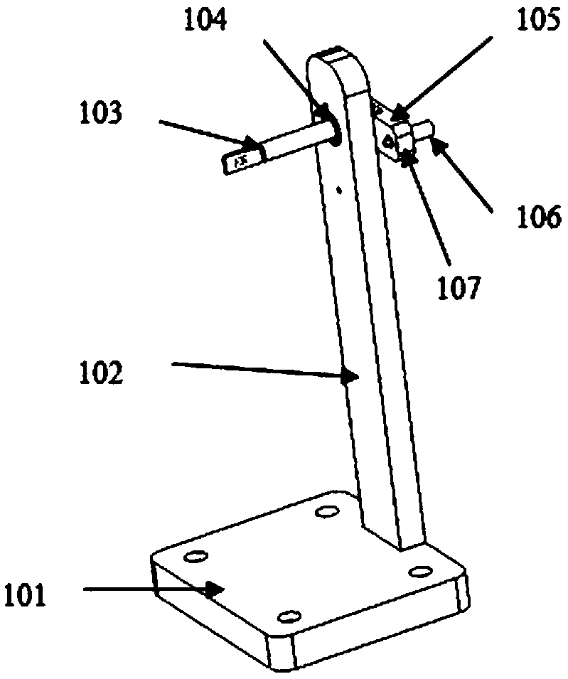
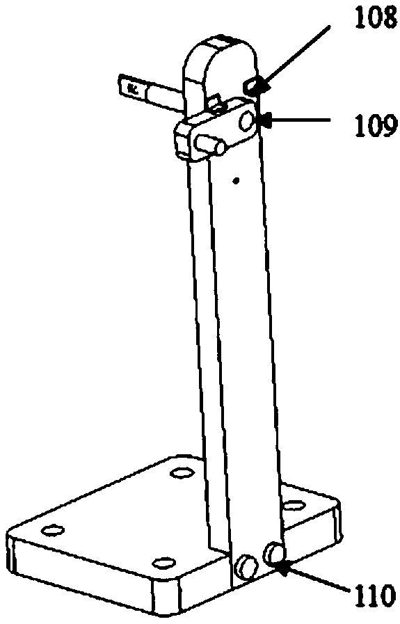
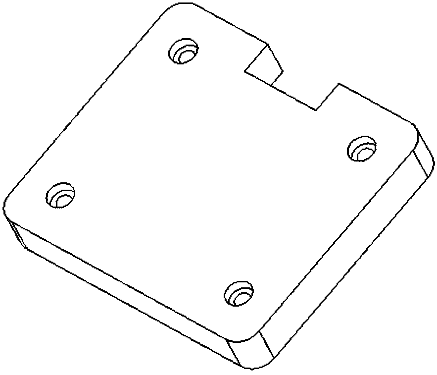
[0024] A device for tensile and bending test of linear terminals of components, see Figure 1 to Figure 11 , the device for the tensile and bending test of the linear lead-out of components includes a horizontal base 101, a vertical bracket 102, a clamp 103, a bearing 104, a rocker 105, a positioning handle 106, a spring 107, and a limit block 108 , fixing screw 109 and connecting screw 110; see figure 1 and figure 2 , the bracket 102 is connected and fixed with the base 101 by a set screw 109; see Figure 6 , the clamp 103 is installed on the bracket 102 through the bearing 104, and the clamp 103 is connected with the rocker 105 through the connecting screw 110; the positioning handle 106 includes a guide section, the spring 107 is set outside the positioning handle 106, and the positioning handle 106 is installed on the rocking bar 105 ; see Figure 10 , the limit block 108 is installed on the bracket 102 and is located above the rocker 105; the positioning handle 106 is...


PUM


Abstract

The invention discloses a device for testing tensile bending resistance of a component line-shaped leading-out end, wherein a support is fixedly connected with a base through a fixing screw; a clamp is installed on the support through a bearing, and the clamp is connected with a rocker through a connecting screw; a positioning handle comprises a guide section, a spring is arranged outside the positioning handle in a sleeved mode, and the positioning handle is arranged on the rocker; a limiting block is arranged on the support and above the rocker; a positioning pin is arranged on the positioning handle, and a positioning hole matched with the positioning pin is formed in the support; during a bending-resistant test, control is conducted through the positioning handle, so that the clamp forplacing a component can rotate, and the leading-out end can be bent under the action of the gravity of a weight; the operation of rotating the positioning handle is simple, the operation time is saved; the magnitude and direction of the bending force can be well controlled; the bending angle of the leading-out end can be accurately controlled through the limiting block during the test; the working efficiency of the tensile bending-resisting test of the leading-out end of the component can be improved; the operation is simple and convenient, the damage to hands by leads is avoided, the loss ofthe samples is reduced, and the accuracy of the test result is improved.

Description

technical field [0001] The present application relates to the technical field of component production, and in particular to a device for tensile and bending tests of linear lead-out ends of components. Background technique [0002] At present, in the production process of components, it is usually necessary to conduct a terminal strength test to determine whether the design and connection method of the terminal can withstand various mechanical stresses encountered during assembly, repair, or handling. The test method in the prior art is to put the product on a simple test device, which includes three parts: a base, a support rod and a board, each part is connected together by screws, and the components are placed on the board during the test. Its lead-out end passes through the hole on the set plate, and when performing a tensile test, hang a weight on the lead-out end, and observe and analyze according to the requirements of the required standards; when performing a tensile...

Claims


Application Information

Patent Timeline
Patent Type & Authority Applications(China)
IPC IPC(8): G01N3/14G01N3/20G01N3/02
CPCG01N3/14G01N3/20G01N3/02
Inventor 哈斯图亚郑文强崔巍段友峰刘小光睢建平张磊王雪
Owner BEIJING INST OF RADIO METROLOGY & MEASUREMENT
Learn More