Demonstration instrument for demonstrating optical refraction and reflection law and measuring index of refraction on blackboard

A technology of catadioptric reflection and refractive index, which is applied in the field of demonstration instruments, can solve the problems of high material hardness requirements and insufficient fineness of the manual sliding platform, and achieve the effect of convenient experimental operation, reduction of production cost and difficulty, and lower hardness requirements

Pending Publication Date: 2019-10-01
NANJING POLYTECHNIC INSITUTE
View PDF0 Cites 4 Cited by
  • Summary
  • Abstract
  • Description
  • Claims
  • Application Information

AI Technical Summary

Problems solved by technology

[0002] Patent applications such as "Demonstrator of Suspended Optical Refractive Law" (Application No. 2019105819888), compared with the previous equipment, it integrates the adjustment components of incident light such as laser pen insertion components and adjustment components into an arc-shaped chute On the sliding platform that slides up, the concentric scale disk and the arc-shaped chute are connected as a whole by radial connecting rods. Moving the sliding platform on the arc-shaped chute can keep the incident light close to the scale disk to a certain extent. The disk surface is aligned with the center of the scale disk, which saves time and improves the efficiency of classroom teaching. However, the manual sliding platform is still not fine enough. The overall structure requires high hardness of the material used to make the demonstrator, so it is worth further innovation

Method used


Image

  • Demonstration instrument for demonstrating optical refraction and reflection law and measuring index of refraction on blackboard
  • Demonstration instrument for demonstrating optical refraction and reflection law and measuring index of refraction on blackboard
  • Demonstration instrument for demonstrating optical refraction and reflection law and measuring index of refraction on blackboard

Examples


Embodiment Construction

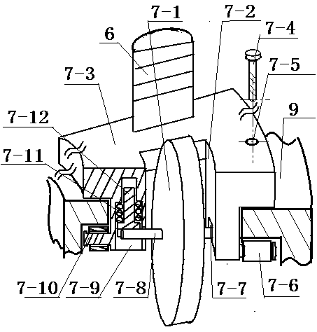
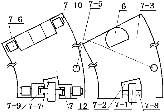
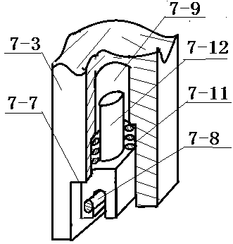
[0018] exist figure 1 Among them, the scale disc 13 is engraved with radian marking lines, median lines, and normal lines. The optical element 12 is clamped on the lower side of the scale disc 13 by the fixture 18. The optical surface of the optical element 12 is aligned with the median line. Flush, the projection laser pointer 1 is inserted in the laser pointer mount 2, the laser pointer mount 2 is mounted on the T-shaped support plate 5, and the collar 4 on the vertical end of the T-shaped support plate 5 is set on the cylindrical rack 6 On the other hand, the adjuster 3 that crosses the two side walls of the collar 4 and is placed in the collar 4 is coupled with the cylindrical rack 6 through a gear, and makes the arc back of the cylindrical rack 6 squeeze against the back of the collar 4 On the inner wall, the strength of the extrusion enables the collar 4 set on the cylindrical rack 6 to be adjusted and moved along the cylindrical rack 6, and can be stabilized at an appro...


PUM


Abstract

The invention provides a demonstration instrument for demonstrating optical refraction and reflection law and measuring index of refraction on a blackboard. The demonstration instrument is composed ofa projection laser pen, laser pen placing and inserting parts, adjusting parts, a lantern ring, a T-shaped support plate, a cylinder-shaped rack, a gear sliding platform assembly, a connecting rod, an arc-shaped sliding chute, magnetic suckers, a Y-shaped bottom plate, an optical element, a scale disk, studs, gaskets, second springs, butterfly nuts, fixing parts and the like. Based on the technology of the invention with the application number 2019105819888, the technical scheme is characterized in that a gear is mounted at one end of a Pi-shaped sliding platform, the rack is formed in the bottom of the arc-shaped sliding chute, the Pi-shaped sliding platform is driven to move on the arc-shaped sliding chute by utilizing tooth coupling, the tiny adjustment for the incidence angle of incident rays is realized, the springs are arranged between the scale disk and the Y-shaped bottom plate for supporting, so that the direction of the face of the scale disk can be conveniently adjusted, the Y-shaped bottom plate and the arc-shaped sliding chute are connected to form a whole, so that the requirement for the hardness of a manufacturing material is reduced, the manufacturing cost and difficulty are reduced, the adjustment for the incident rays and the face of the scale disk is facilitated, time is further saved, and the classroom teaching efficiency is improved.

Description

technical field [0001] The invention relates to a demonstration instrument for demonstrating the law of optical refraction and refraction on a blackboard to measure the refractive index, and belongs to the technical field of experiment teaching. Background technique [0002] Patent applications such as "Demonstrator of Suspended Optical Refractive Law" (Application No. 2019105819888), compared with the previous equipment, it integrates the adjustment components of incident light such as laser pen insertion components and adjustment components into an arc-shaped chute On the sliding platform that slides up, the concentric scale disk and the arc-shaped chute are connected as a whole by radial connecting rods. Moving the sliding platform on the arc-shaped chute can keep the incident light close to the scale disk to a certain extent. Aligning the disk surface with the center of the scale disk saves time and improves the efficiency of classroom teaching, but the manual sliding pl...

Claims


Application Information

Patent Timeline
Patent Type & Authority Applications(China)
IPC IPC(8): G09B23/22
CPCG09B23/22
Inventor 葛亮
Owner NANJING POLYTECHNIC INSITUTE
Why Eureka
Try Eureka