Eureka AIR delivers breakthrough ideas for toughest innovation challenges, trusted by R&D personnel around the world.

A motor, an electric power steering device, and a method of manufacturing the motor

A manufacturing method and motor technology, applied in the direction of electromechanical devices, electric components, electrical components, etc., can solve problems such as increased component costs, achieve the effect of easy fixing and reduced manufacturing costs

Pending Publication Date: 2019-10-01
NIDEC CORP
View PDF5 Cites 3 Cited by
  • Summary
  • Abstract
  • Description
  • Claims
  • Application Information

AI Technical Summary

Problems solved by technology

[0003] However, in the above-mentioned fixing method of the bus bar holder, it is necessary to perform high-precision processing on the parts including the bearing holder as the part on the other side.
Along with the complexity of the shape, in addition to the increase in the cost of parts, positional accuracy during assembly is also required

Method used


Image

  • A motor, an electric power steering device, and a method of manufacturing the motor
  • A motor, an electric power steering device, and a method of manufacturing the motor
  • A motor, an electric power steering device, and a method of manufacturing the motor

Examples


Embodiment approach

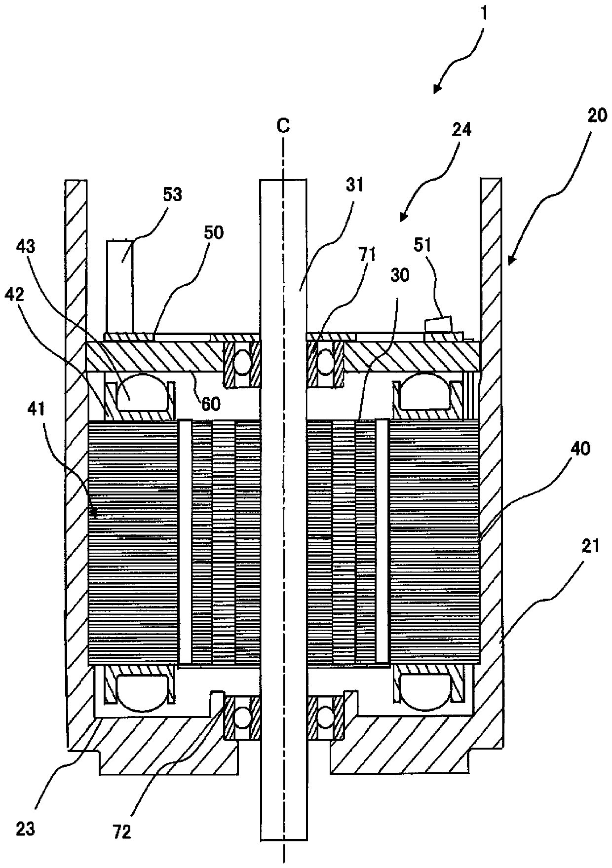
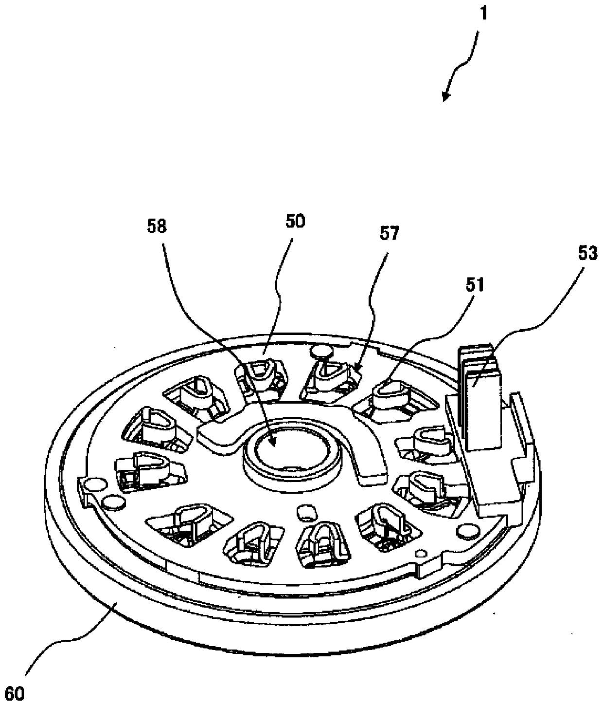
[0021] Such as figure 1 As shown, the motor 1 has a shaft 31 , a rotor 30 , a stator 40 , a housing 20 , a bus bar holder 50 and a bearing holder 60 .

[0022] The shaft 31 extends along the central axis C, and is rotatably supported around the central axis C by an upper bearing 71 and a lower bearing 72 . The rotor 30 is fixed to the shaft 31 and rotates around the central axis C together with the shaft 31 .

[0023] The stator 40 is arranged to face the rotor 30 on the radially outer side of the rotor 30 . The stator 40 has a stator core 41 , an insulator 42 and a coil wire 43 . The insulator 42 is attached to the teeth (not shown) of the stator core 41 . The coil wire 43 is an example of a conductive part, is made of a conductive wire, and is wound around the teeth via the insulator 42 . Lead wires drawn upward from the stator 40 from the coil wire 43 wound on the stator 40 are connected to a bus bar 51 described later.

[0024] The housing 20 is disposed radially outs...


PUM


Abstract

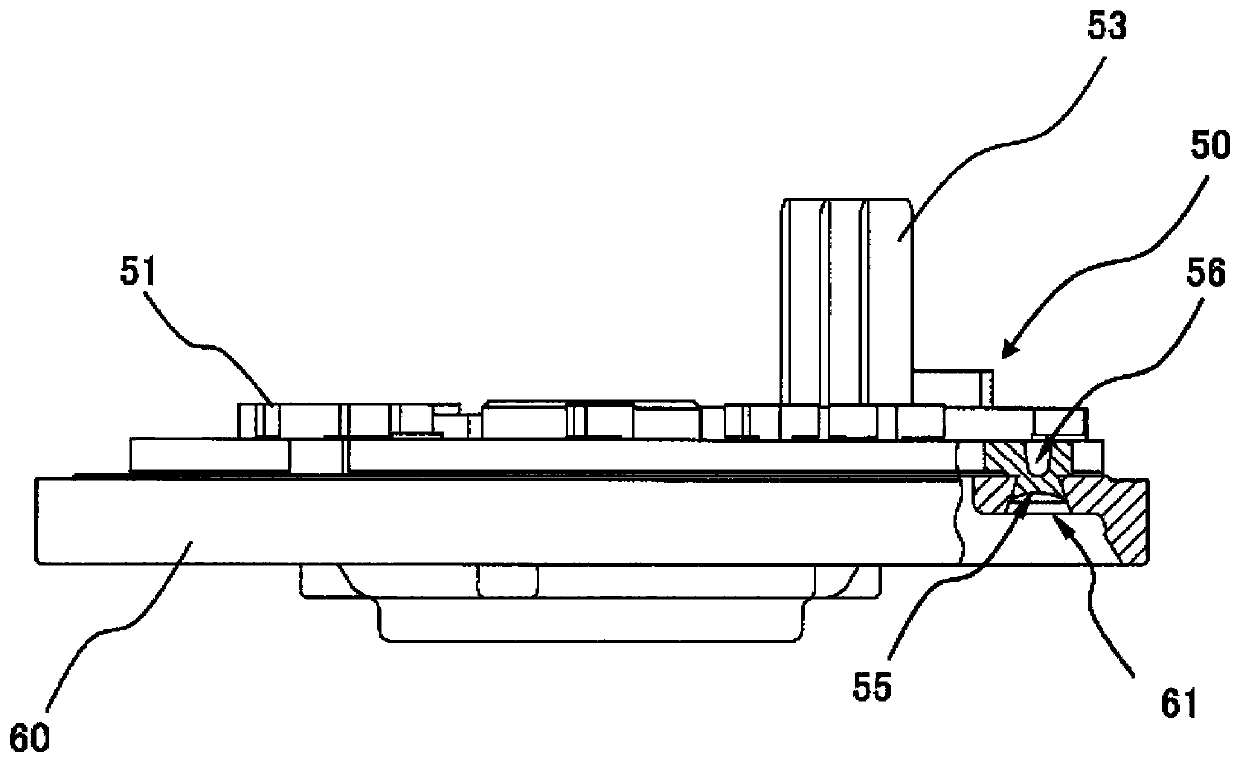
A motor, an electric power steering device, and a method of manufacturing the motor are provided. In the motor, a bus bar holder (50) supports a bus bar (51) connected to a conductive portion of a stator. A bearing retainer (60) is coupled to the bus bar holder (50). A through hole (61) is provided in the bearing retainer (60). A convex portion (55) is provided in the bus bar holder (50), protrudes into the through hole (61), and is fitted into the through hole (61). A concave portion (56) is recessed from the opposite side of the protruding direction of the convex portion (55) towards the protruding direction.

Description

technical field [0001] The present invention relates to a motor, an electric power steering device, and a method for manufacturing the motor. Background technique [0002] In a motor, there is known a structure in which a bus bar holder is directly fixed to a stator (see Japanese Patent No. 5064401). In recent years, a structure in which the bus bar holder is fixed to the upper part of the bearing holder has been adopted. As a method of fixing the bus bar holder to the bearing holder, for example, there is a method of processing the bus bar holder into a predetermined shape and inserting, press-fitting, or welding the shaped part into the bearing holder. [0003] However, in the above-described method of fixing the bus bar holder, it is necessary to perform high-precision machining on the components including the bearing holder as the component on the other side. Along with the complexity of the shape, in addition to an increase in component cost, positional accuracy at th...

Claims


Application Information

Patent Timeline
Patent Type & Authority Applications(China)
IPC IPC(8): H02K5/22H02K5/173
CPCH02K5/225H02K5/1732
Inventor 加藤明利瀬口敬史小川幸祐大西达也安藤博典
Owner NIDEC CORP
Why Eureka
Eureka Blog
Learn More