Novel fiber placement head

A new type of silk laying head technology, applied in the field of new silk laying head, can solve the problems of short life of cutter and chopping board, lower molding speed, poor molding quality, etc., and improve process adaptability, equipment accessibility, and response Time reduction, effect of reducing laying head size

Pending Publication Date: 2019-10-08
肖睿
View PDF0 Cites 5 Cited by
  • Summary
  • Abstract
  • Description
  • Claims
  • Application Information

AI Technical Summary

Problems solved by technology

[0012] The present invention solves the problem that the existing automatic silk laying machine's silk path cutter collides with the metal cutting board at high speed when completing the wire cutting work. There are relatively large requirements for the hardness of the prepreg and the process of laying prepreg with tension on the concave surface, the defect of fiber bridging often occurs, resulting in the technical problems of reduced molding speed and poor molding quality, and then provides a new type of prepreg. silk head

Method used


Image

  • Novel fiber placement head
  • Novel fiber placement head
  • Novel fiber placement head

Examples


Embodiment 1

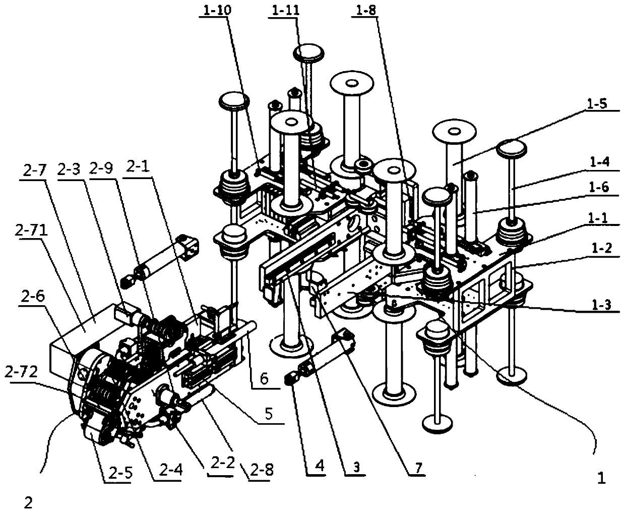
[0052] Embodiment 1, a new type of silk-laying head, two linear guide rails 3 are arranged in parallel on the yarn box 1, a slider 5 is installed on the floating mechanism 2 of the silk-laying head, and the floating mechanism 2 of the silk-laying head communicates with the The linear guide rail 3 is used in conjunction with one end of the pressing cylinder 4 connected with the yarn box 1, and the other end of the pressing cylinder 4 is connected with the floating mechanism 2 of the laying head, and the pressing cylinder 4 drives the floating mechanism 2 of the laying head to slide on the linear guide rail 3.

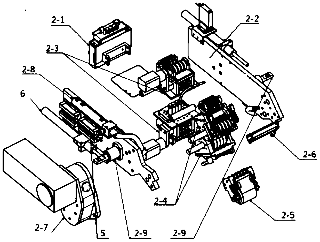
[0053] The laying head floating mechanism 2 includes: terminal mounting plate 2-1, vertical plate 2-2, tension reducing mechanism 2-3, tow actuating device 2-4, flexible pressure roller 2-5, heating lamp 2 -6. Driving mechanism 2-7, vortex tube 2-8 and compression cylinder hinged seat 2-9, vertical plates 2-2 are arranged on both sides of the terminal mounting plate 2-1, ...

Embodiment 2

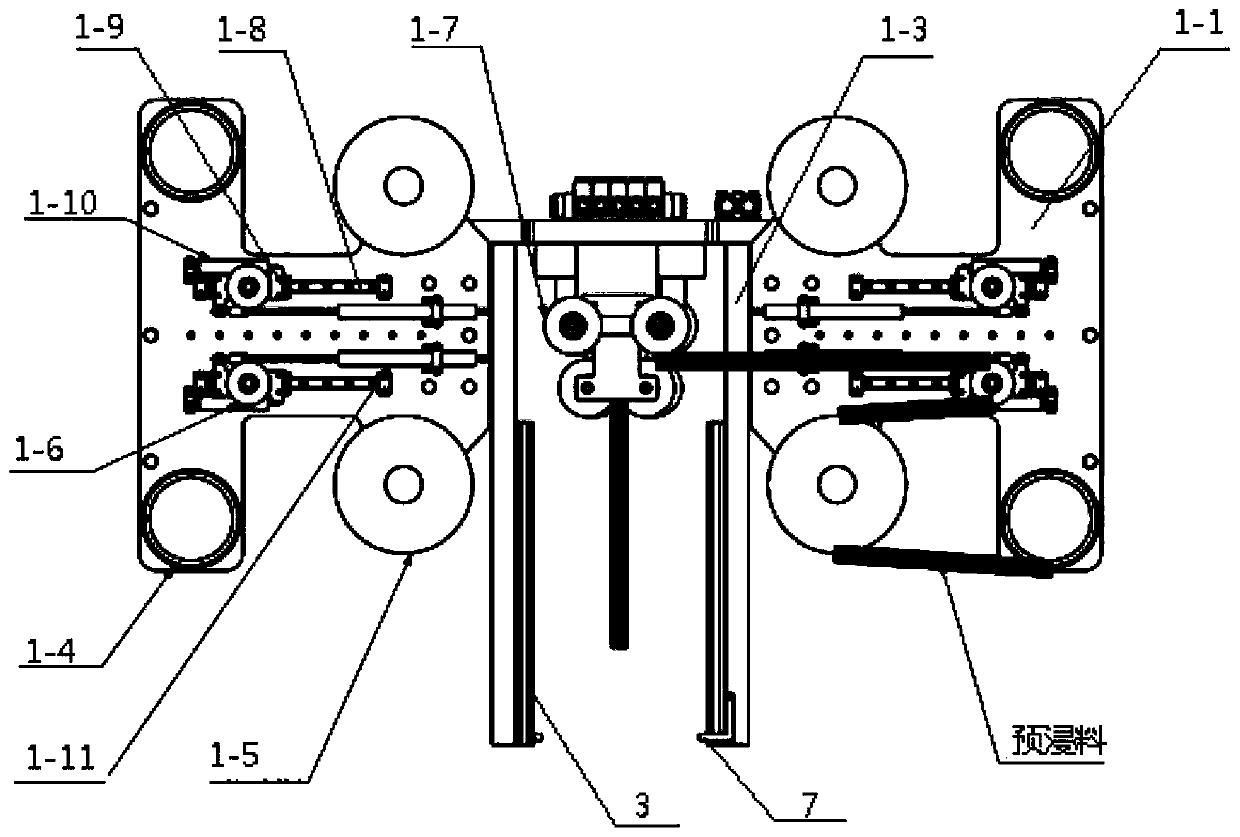
[0054] Embodiment 2, the yarn box 1 includes: a mounting plate 1-1, a connecting support plate 1-2, and a U-shaped connecting plate 1-3, and the left and right sides of the U-shaped connecting plate 1-3 are provided with two mutual Parallel installation boards 1-1, the other end of the installation boards 1-1 on the same side are connected by connecting support boards 1-2, each installation board 1-1 is provided with two yarn releasing and film collecting mechanisms, U-shaped connecting boards A slide rail 3 is arranged on the inner wall of 1-3, and one end of the pressing cylinder 4 is connected with the outer wall of the U-shaped connecting plate 1-3, and a limit stop 7 is installed on the U-shaped connecting plate 1-3, and the floating mechanism 2 of the laying head The output end of the buffer cylinder 6 is used in conjunction with the limit stopper 7. In this way, multiple yarn collection mechanisms are placed on the same mounting plate 1-1 to reduce the overall size and s...

Embodiment 3

[0055] Embodiment 3, the yarn collection mechanism includes: yarn unwinding shaft 1-4, film collection shaft 1-5, tension measurement shaft 1-6, yarn box guide wheel 1-7, measurement slide rail 1-8, measurement slide Block 1-9, tension spring 1-10 and resistance ruler 1-11, on the described mounting plate 1-1, yarn unwinding shaft 1-4, film collecting shaft 1-5 and measuring slide rail 1-8 are installed, measuring slide A measuring slider 1-9 is installed on the rail 1-8, a tension measuring shaft 1-6 is installed on the measuring slider 1-9, one end of the tension spring 1-10 is connected with the measuring slider 1-9, and the tension spring 1-10 The other end is connected to the mounting plate 1-1, the resistance scale 1-11 is fixedly installed on the mounting plate 1-1, the moving end of the resistance scale 1-11 is connected to the measuring slider 1-9, and the U-shaped connecting plate 1-3 is internally closed Yarn box guide wheels 1-7 are arranged at the end of the bobbi...


PUM


Abstract

The invention relates to a novel fiber placement head, and belongs to the technical field of fiber placement machines. The novel fiber placement head comprises a yarn box and a fiber placement head floating mechanism, wherein two linear guide rails are arranged on the yarn box in parallel; sliding blocks are mounted on the fiber placement head floating mechanism; the fiber placement head floatingmechanism is used in match with the linear guide rails through the sliding blocks; one end of a compaction air cylinder is connected with the yarn box while the other end of the compaction air cylinder is connected with the fiber placement head floating mechanism; the fiber placement head floating mechanism is driven by the compaction air cylinder to be slid on the linear guide rails. According tothe yarn box disclosed by the invention, paying-off of yarns of four groups of prepreg rolls, that is, eight prepreg rolls can be realized simultaneously and cannot interfere with each other; two mounting plates which are parallel to each other are arranged on the left side and the right side of a U-shaped connecting plate; and two yarn paying-off film-collecting mechanisms are arranged on each of the mounting plates. Due to the arrangement, the whole size of the yarn box is greatly reduced, so that the phenomenon that interference between a concave curved surface and a die occurs when the concave curved surface with a narrow space can be prevented. According to the novel fiber placement head disclosed by the invention, a novel filament bundle actuation device is adopted, so that a wrapangle of the fiber placement head is reduced, and the technical problem of lack of accessibility is further solved.

Description

technical field [0001] The invention relates to the technical field of silk laying machines, in particular to a novel silk laying head. Background technique [0002] Automatic wire laying technology has been widely used and developed in the past 30 years, and has become a typical representative of composite material forming automation technology. Compared with automatic tape laying technology, automatic wire laying process has better adaptability and can be used to manufacture composite parts with complex curved surfaces. As far as the wire laying machine is concerned, the configuration of the laying head of each manufacturer is different but the basic functions are similar. They can complete the roller laying, yarn feeding, yarn breaking, yarn stopping, tension control, temperature control and laying pressure control, etc. Features. [0003] There are five main components that require tension in the laying head, and they are in the order of the yarn path from the yarn box...

Claims


Application Information

Patent Timeline
Patent Type & Authority Applications(China)
IPC IPC(8): B29C70/30B29C70/54
CPCB29C70/30B29C70/54
Inventor 肖睿
Owner 肖睿
Why Eureka
Try Eureka