An automatic dispensing mechanism

A material distribution mechanism and automatic technology, applied in conveyors, conveyor objects, transportation and packaging, etc., can solve problems such as poor positioning effect, materials easily deviate from the conveyor belt, and increased labor costs.

Active Publication Date: 2021-04-30
BOZHON PRECISION IND TECH CO LTD
View PDF3 Cites 0 Cited by
  • Summary
  • Abstract
  • Description
  • Claims
  • Application Information

AI Technical Summary

Problems solved by technology

It generally includes functions such as support, loading, and feeding. The support adopts a general flat pallet, and the feeding is carried by a conveyor belt or manually. When the support plate is fixed, it needs to be manually carried, which increases labor costs, or it is placed directly on the conveyor belt. The positioning effect is not good Well, material tends to drift off the conveyor belt

Method used


Image

  • An automatic dispensing mechanism
  • An automatic dispensing mechanism
  • An automatic dispensing mechanism

Examples


Embodiment

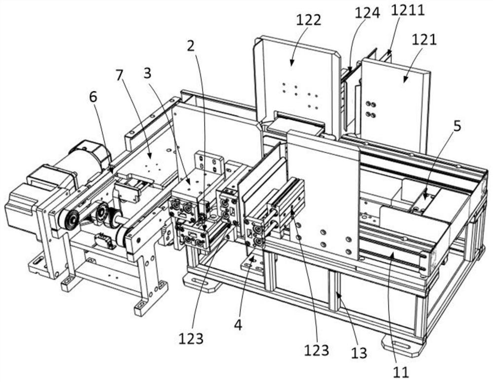
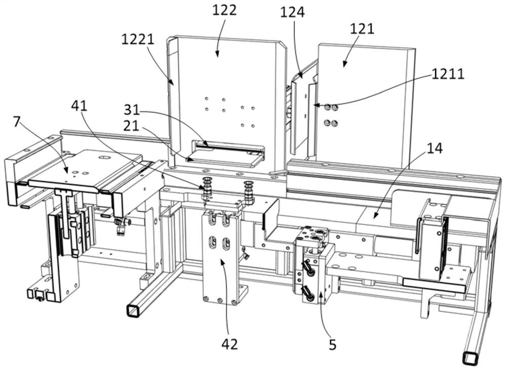
[0079] This embodiment provides an automatic material distribution mechanism, such as Figure 1-2 shown, including:

[0080] First frame, described first frame comprises cross bar 11, side plate, support leg 13, mounting plate 14, and described cross bar 11 is positioned at the both sides of described first frame, and the lower part of described cross bar 11 The surface is fixed with a mounting plate 14, the outer surface of the cross bar 11 is fixed with a side plate, and the lower surface of the mounting plate 14 is fixedly connected with the support leg 13 near the outer edge; one end of the first frame is used for The tray is loaded, and the other end is used for splitting the tray. There are two groups of side plates, including the first side plate 121 located at the end of the first frame for loading the tray, and the first side plate 121 located at the second end of the first frame. The second side plate 122 of an end that is used for the dismantling of tray of a frame...


PUM


Abstract

The present application relates to an automatic material distributing mechanism, which is characterized in that it includes: a first frame with a feeding position and a material distributing position, and the feeding position is used to accept a stack of material trays; The bottom is used to accept the piles of trays transferred from the feeding position; the material distribution component is arranged at the material distribution position, and the material distribution component includes material distribution plates located on both sides of the material distribution position and used to push the material distribution plate A moving material distribution plate pushing device, which can drive the material distribution plate to clamp the flange of the second-bottom material tray in the pile of material trays, and an adsorption component for separating the material trays is also arranged at the material distribution position; The push assembly is used to push the tray step by step. A large number of trays can be stacked at the feeding tray of the present invention, reducing the number of times of feeding, reducing the workload, and increasing productivity; by absorbing a tray from the bottom of the stack of trays and limiting other trays with the material distribution assembly, it is realized Automatic distribution.

Description

technical field [0001] The application belongs to the technical field of automatic feeding devices, and in particular relates to an automatic feeding mechanism. Background technique [0002] In the machinery industry, in order to complete the support, transportation and accurate positioning of the tray, various loading and unloading mechanisms are used. Using a suitable loading and unloading mechanism can save space, carry accurately and simplify operation. Most of the plastic tray feeding mechanisms commonly used today are targeted, and most of them are single suction trays. Each feeding mechanism is only for a single suction tray of the same size, and the size is specific. It generally includes functions such as support, loading, and feeding. The support adopts a general flat pallet, and the feeding is carried by a conveyor belt or manually. When the support plate is fixed, it needs to be manually carried, which increases labor costs, or it is placed directly on the conve...

Claims


Application Information

Patent Timeline
Patent Type & Authority Patents(China)
IPC IPC(8): B65G47/82B65G47/91B65G47/24
CPCB65G47/24B65G47/82B65G47/91B65G2201/0267
Inventor 刘建军
Owner BOZHON PRECISION IND TECH CO LTD
Why Eureka
Try Eureka