Device facilitating assembling and disassembling of free end of high-rotating-speed spinning revolving cup

A free-end, high-speed technology, used in free-end spinning machines, spinning machines, spinning machines with continuous winding, etc., can solve the problems of low maintenance efficiency and serious wear of the spinning rotor. The effect of improving efficiency, improving maintenance efficiency and simple operation

Active Publication Date: 2019-10-08
济宁精忠纺织有限公司
View PDF11 Cites 0 Cited by
  • Summary
  • Abstract
  • Description
  • Claims
  • Application Information

AI Technical Summary

Problems solved by technology

[0002] Air spinning is through the high-speed rotating cup in the spinning device and the negative pressure in the cup to complete fiber transportation, cohesion, merging, and twisting into yarn. Therefore, the speed of the spinning rotor determines the spinning efficiency. In the spinning device at the free end, for example, when the speed is above 130,000 / min, the spinning rotor is usually rotated magnetically to meet the radial deflection and support, but in order to optimize the anti-rotation force and inertia, the spinning rotor is usually rotated. The weight of the spinning rotor is reduced, so that the thickness of the spinning rotor is relatively thin. Therefore, at the same speed, the wear of the thinner spinning rotor will be serious, and it needs to be replaced frequently.
[0003] Existing spinning rotors are usually connected to the rotor shaft by threads or pins. This connection method requires extensive disassembly of the equipment when replacing the spinning rotor, and the maintenance efficiency is low.

Method used


Image

  • Device facilitating assembling and disassembling of free end of high-rotating-speed spinning revolving cup
  • Device facilitating assembling and disassembling of free end of high-rotating-speed spinning revolving cup
  • Device facilitating assembling and disassembling of free end of high-rotating-speed spinning revolving cup

Examples


Embodiment Construction

[0028] The following will clearly and completely describe the technical solutions in the embodiments of the present invention with reference to the accompanying drawings in the embodiments of the present invention. Obviously, the described embodiments are only some, not all, embodiments of the present invention. Based on the embodiments of the present invention, all other embodiments obtained by persons of ordinary skill in the art without making creative efforts belong to the protection scope of the present invention.

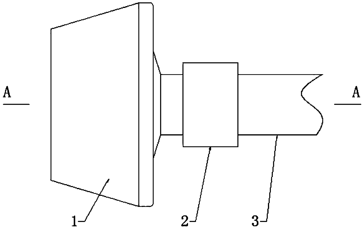
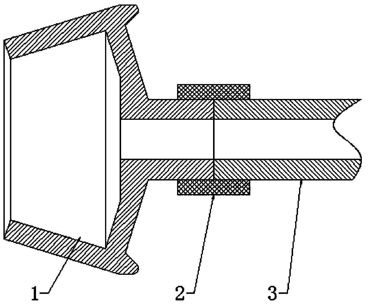
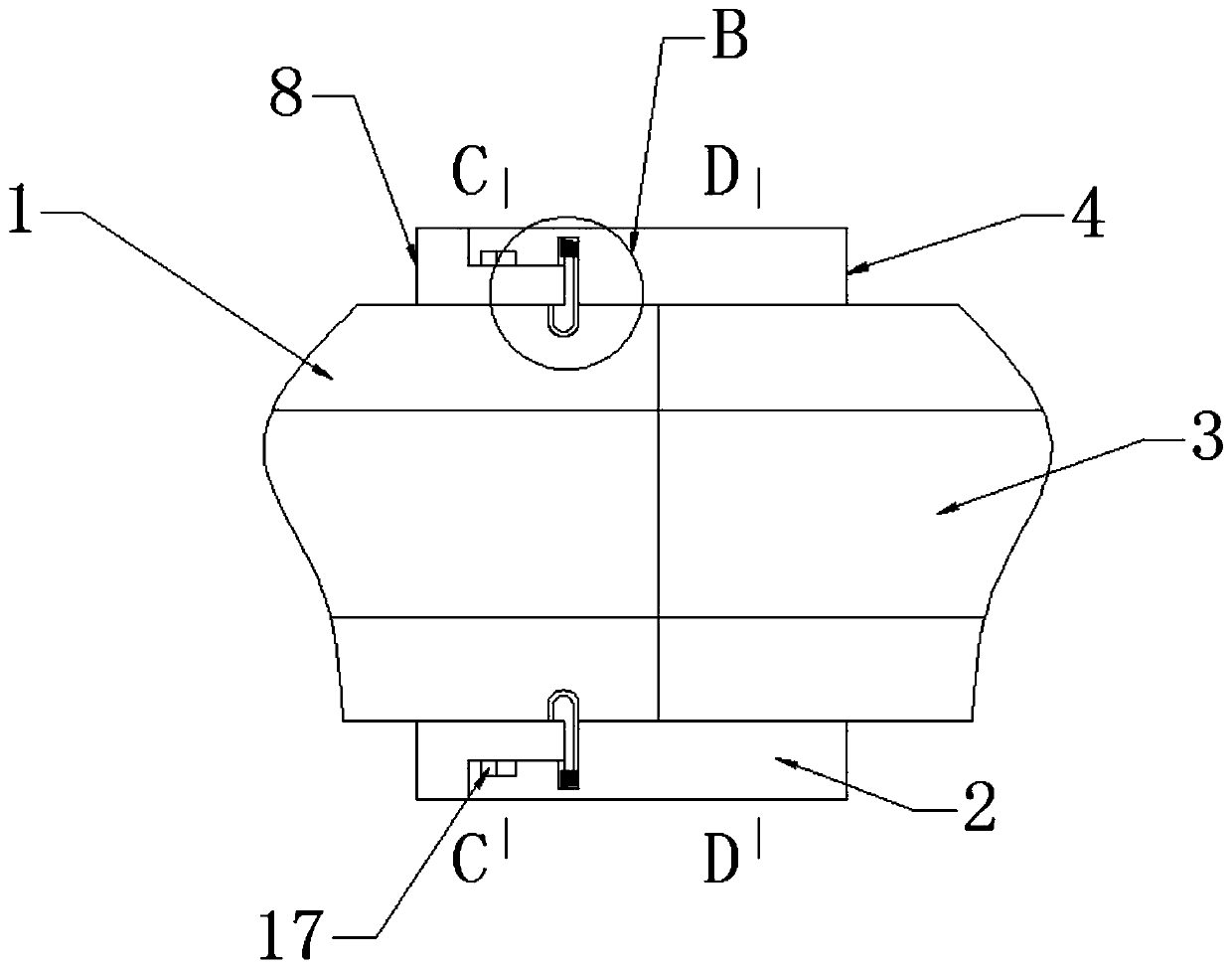
[0029] Such as Figure 1-8 As shown, according to the technical solution provided by the present invention: a device that facilitates the installation and disassembly of the free end of the high-speed spinning rotor, including the spinning rotor 1, the fixed part on the spinning rotor 1 is connected to the rotor shaft through the connecting mechanism 2 3 fixed connections.

[0030] The connection mechanism 2 includes a fixed sleeve 4. The fixed part on the sp...


PUM


Abstract

The invention relates to the field of spinning revolving cups, and discloses a device facilitating assembling and disassembling of a free end of a high-rotating-speed spinning revolving cup. The device facilitating assembling and disassembling of the free end of the high-rotating-speed spinning revolving cup comprises the spinning revolving cup, wherein a fixing portion on the spinning revolving cup is fixedly connected with a rotor shaft through a connecting mechanism, the connecting mechanism comprises a fixing sleeve, and the fixing portion on the spinning revolving cup and one end of the rotor shaft extend into the fixing sleeve and are matched with each other. The fixing sleeve is fixedly connected with the rotor shaft, and certain force is applied to the fixing sleeve, then the fixing sleeve can be installed on the rotor shaft, the fixing sleeve rotates until the position of a baffle corresponds to the position of a groove in the rotor shaft, and the baffle is ejected out under the action of a torsion spring and is in clamped connection with the groove; and the rotor shaft is separated from the fixing sleeve without disassembling the machine, and the rotor shaft only needs torotate in the rotating direction of the rotor shaft after the machine stops, the baffle is pressed into the mounting groove and is taken out, disassembling is simple and conveniently, the repair efficiency is improved effectively, and the benefit of a plant is increased.

Description

technical field [0001] The invention relates to the field of spinning rotors, in particular to a device for facilitating the installation and disassembly of the free ends of high-speed spinning rotors. Background technique [0002] Air spinning is through the high-speed rotating cup in the spinning device and the negative pressure in the cup to complete fiber transportation, cohesion, merging, and twisting into yarn. Therefore, the speed of the spinning rotor determines the spinning efficiency. In the spinning device at the free end, for example, when the speed is above 130,000 / min, the spinning rotor is usually rotated magnetically to meet the radial deflection and support, but in order to optimize the anti-rotation force and inertia, the spinning rotor is usually rotated. The weight of the spinning rotor is reduced, so that the thickness of the spinning rotor is relatively thin. Therefore, at the same speed, the wear of the thinner spinning rotor will be serious, and it ne...

Claims


Application Information

Patent Timeline
Patent Type & Authority Applications(China)
IPC IPC(8): D01H4/12
CPCD01H4/12
Inventor 黄泽
Owner 济宁精忠纺织有限公司
Why Eureka
Try Eureka