Electric power pipe rack and anti-flooding wall co-building structure and construction method thereof

A technology of power pipe gallery and construction method, which is applied in the direction of basic structure engineering, underwater structures, dikes, etc., can solve the problems of high demolition costs, large project investment, large land area, etc., and improve construction safety and standards, safety The effect of high performance and reduced engineering investment

Pending Publication Date: 2019-10-08
CHANGJIANG SURVEY PLANNING DESIGN & RES
View PDF0 Cites 6 Cited by
  • Summary
  • Abstract
  • Description
  • Claims
  • Application Information

AI Technical Summary

Problems solved by technology

The total construction period of the whole scheme is 8 months, and the investment cost is high
When laying according to the existing plan, the land occupation width on the plane is relatively wide, and 2500m of embankment management buildings along the line need to be demolished 2 , high demolition costs
It can be seen from this that the power pipe gallery and the flood control wall are constructed separately and independently, and need to be excavated and constructed separately. Not only does the land use a large area, but the embankment management buildings along the line need to be demolished, and the construction period is long and the project investment is large.

Method used


Image

  • Electric power pipe rack and anti-flooding wall co-building structure and construction method thereof
  • Electric power pipe rack and anti-flooding wall co-building structure and construction method thereof
  • Electric power pipe rack and anti-flooding wall co-building structure and construction method thereof

Examples


Embodiment Construction

[0031] The implementation of the present invention will be described in detail below in conjunction with the examples of implementation, but they do not constitute a limitation of the present invention, and are only examples. At the same time, the advantages of the present invention will become clearer and easier to understand.

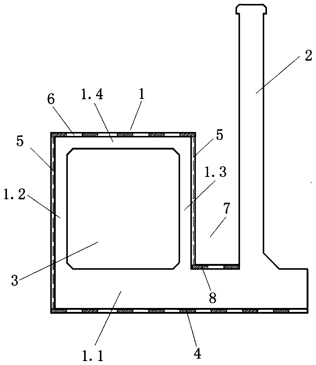
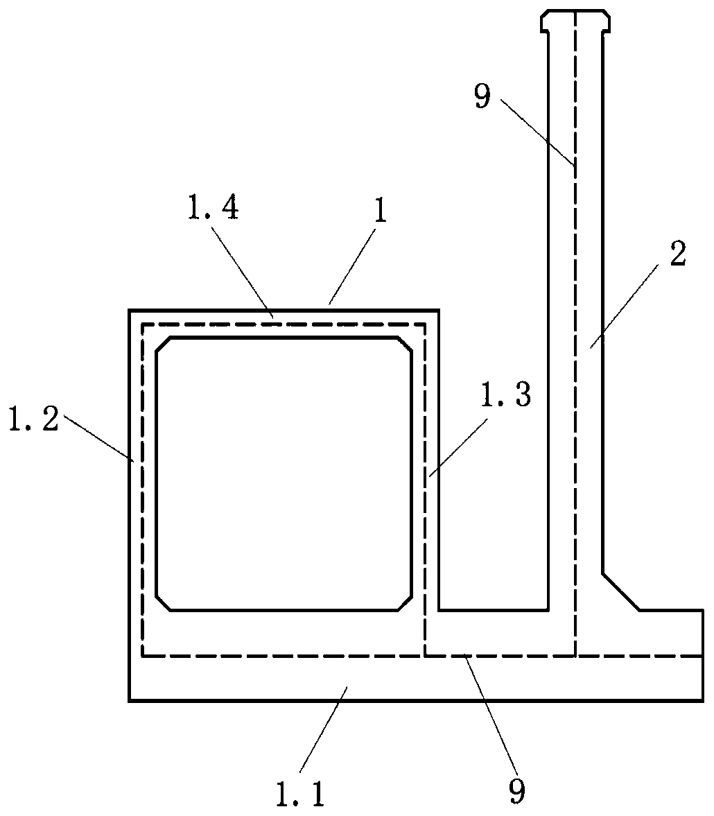
[0032] Such as figure 1 The shown co-construction structure of a power pipe gallery and a flood control wall designed by the present invention includes a power pipe gallery body 1 and a flood control wall 2. The power pipe gallery body 1 is a rectangular frame structure, including a bottom plate 1.1, a first Pipe gallery side wall 1.2, second pipe gallery side wall 1.3, and pipe gallery roof 1.4, the first pipe gallery side wall 1.2 is set on one side of the bottom plate 1.1 in the width direction, and the flood control wall 2 is set on the bottom plate 1.1 in the width direction On the other side, the second pipe gallery side wall 1.3 is arranged in...


PUM


Abstract

The invention discloses an electric power pipe rack and anti-flooding wall co-building structure and a construction method thereof. The structure comprises an electric power pipe rack body and an anti-flooding wall; the electric power pipe rack body comprises a bottom plate, a first pipe rack side wall, a second pipe rack side wall and a pipe rack top plate; the first pipe rack side wall is arranged on the side in the width direction of the bottom plate; the anti-flooding wall is arranged on the other side in the width direction of the bottom plate; the second pipe rack side wall is arranged on the middle portion of the bottom plate; the pipe rack top plate is arranged on the top face between the first pipe rack side wall and the second pipe rack side wall; and a hollow channel for a pipeline to pass through is defined among the bottom plate, the first pipe rack side wall, the pipe rack top plate and the second pipe rack side wall. The structure intensively utilizes the city building land, improves the electric power pipe rack building safety and standard, shortens the construction period, reduces the engineering investments and reduces disassembling of rooms for along-the-line dike management.

Description

technical field [0001] The invention relates to the technical field of water conservancy projects, in particular to a joint construction structure of a power pipe gallery and a flood control wall and a construction method thereof. Background technique [0002] According to the "Code for Design of Embankment Engineering" (GB50286-2013), the construction of earth embankments is often restricted due to expensive land in cities, land occupation or soil acquisition for demolition, and flood walls can be used as soil and water retaining structures, mostly made of reinforced concrete Structure, the structural form is mostly gravity type, cantilever type, buttress type, reinforced type, empty box type and other structural forms. In the suburbs of cities, high-voltage transmission lines are mostly laid on the side of the road in the form of ground poles and towers. With the continuous development of the city, the original road width can no longer meet the traffic requirements, so the...

Claims


Application Information

Patent Timeline
Patent Type & Authority Applications(China)
IPC IPC(8): E02D29/045E02D31/02E02B3/10E02B3/16
CPCE02B3/10E02B3/16E02D29/10E02D31/025Y02A20/00
Inventor 朱敏董志超汪小茂陈飞罗伟石湛闫鸣霄陈荣魏莱陈涛
Owner CHANGJIANG SURVEY PLANNING DESIGN & RES
Why Eureka
Try Eureka