An infrared focal plane array and an infrared thermal imaging system based on the infrared focal plane array

An infrared focal plane and infrared thermal imaging technology, which is applied in the field of infrared thermal imaging, can solve the problems of complex process steps, high blind element rate of devices, and high difficulty in manufacturing infrared thermal imagers, and achieves low cost and avoids 1/f noise. , the effect of reducing the thermal response time

Active Publication Date: 2021-03-30
UNIV OF ELECTRONICS SCI & TECH OF CHINA
View PDF5 Cites 0 Cited by
  • Summary
  • Abstract
  • Description
  • Claims
  • Application Information

AI Technical Summary

Problems solved by technology

However, the infrared thermal imager based on the dual-material cantilever beam structure design still has problems such as high manufacturing difficulty, complicated process steps, and high blind element rate of the device.

Method used


Image

  • An infrared focal plane array and an infrared thermal imaging system based on the infrared focal plane array
  • An infrared focal plane array and an infrared thermal imaging system based on the infrared focal plane array
  • An infrared focal plane array and an infrared thermal imaging system based on the infrared focal plane array

Examples


Embodiment 1

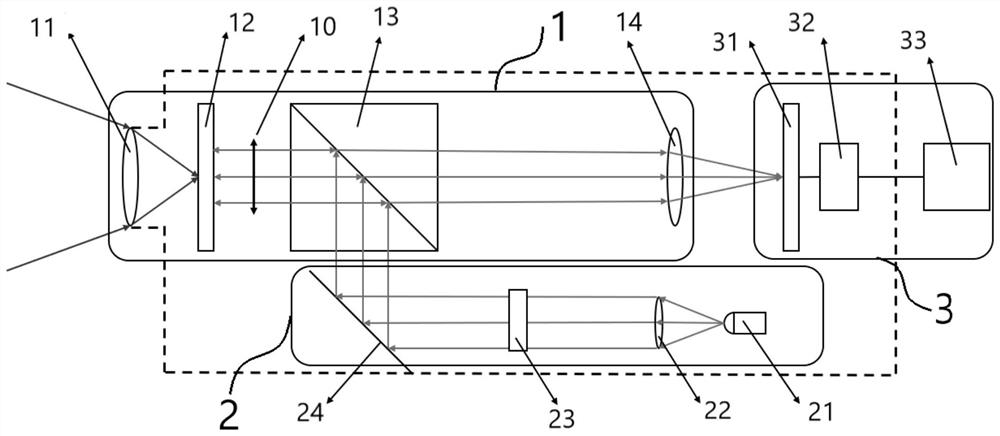
[0066] This embodiment provides an infrared thermal imaging system, such as figure 1 As shown, it includes a wavelength conversion module (1), a readout signal generation module (2) and an imaging display module (3);

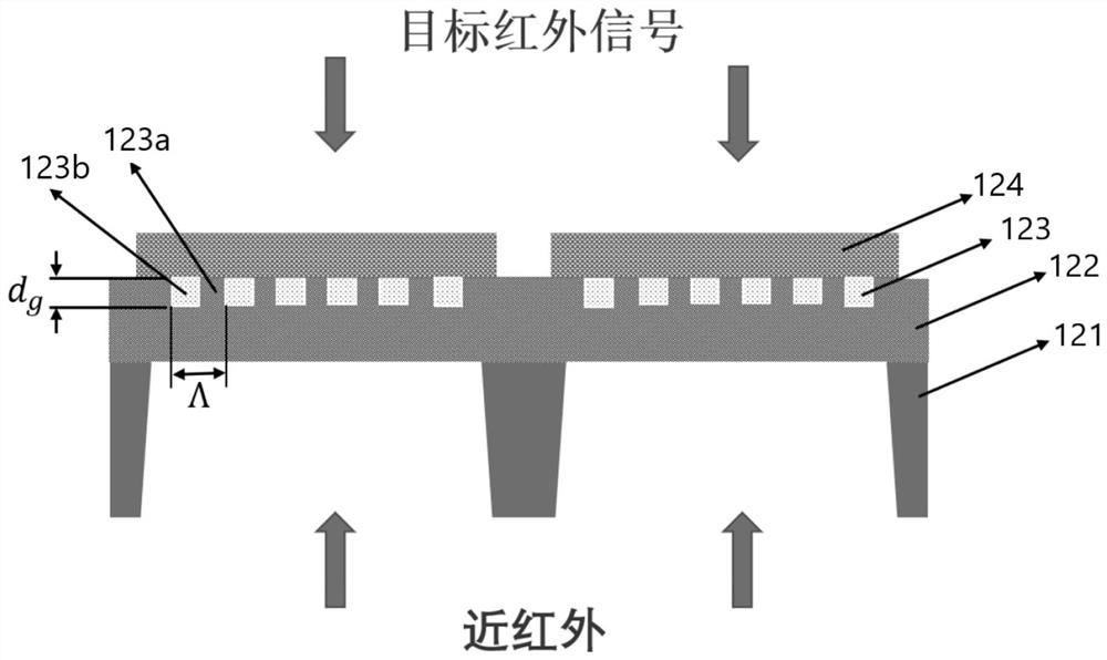
[0067] The wavelength conversion module (1) includes an infrared lens (11), an infrared focal plane array (12), a polarizer (10), and a first beam splitter (13) arranged sequentially along the optical path, wherein the infrared focal plane The planar array (12) includes several periodically arranged array units, and each array unit includes a substrate (121), a thermal insulation support layer (122), a sub-wavelength grating structure and an infrared absorption layer ( 124), opening a window on the back of the substrate (121) corresponding to the region where the sub-wavelength grating structure is located so that light enters the sub-wavelength grating structure through the heat-insulating support layer (122);

[0068] The readout signal generating module (2) ...

Embodiment 2

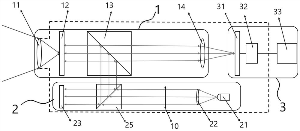
[0092] This embodiment provides an infrared thermal imaging system, such as figure 2 As shown, it includes a wavelength conversion module (1), a readout signal generation module (2) and an imaging display module (3);

[0093] The wavelength conversion module (1) includes an infrared lens (11), an infrared focal plane array (12) and a first beam splitter (13) arranged sequentially along the optical path, wherein the infrared focal plane array (12) includes several array units arranged periodically, each array unit includes a substrate (121), a thermal insulation support layer (122), a sub-wavelength grating structure and an infrared absorption layer (124) arranged sequentially from top to bottom, and the substrate ( On the back of 121), there is a window corresponding to the area where the sub-wavelength grating structure is located so that light enters the sub-wavelength grating structure through the heat-insulating support layer (122);

[0094] The readout signal generating...


PUM


Abstract

The invention discloses an infrared focal plane array and an infrared thermal imaging system based on the infrared focal plane array, belonging to the field of infrared thermal imaging. The infrared focal plane array includes several periodically arranged array units, and each array unit includes a substrate, a thermal insulation support layer, a sub-wavelength grating structure and an infrared absorption layer. The infrared thermal imaging system based on the infrared focal plane array includes a wavelength conversion module, a readout signal generation module and an imaging display module; the core component of the wavelength conversion module is an infrared focal plane array; the infrared radiation from the target is focused on the focal plane, The infrared image information of the target is converted into temperature distribution information on the focal plane array; the readout signal generating module is used to generate linearly polarized narrow-band near-infrared light and make it reflected by the infrared focal plane array and then enter the imaging display module to realize the visualization of the target object . The invention realizes the thermal imaging system design of large area array, high pixels, low cost and fast response.

Description

technical field [0001] The invention belongs to the technical field of infrared thermal imaging, and in particular relates to an infrared focal plane array and an infrared thermal imaging system based on the infrared focal plane array. Background technique [0002] Infrared thermal imaging technology has more and more applications in military, aerospace, medical diagnosis, automatic driving, investigation and other fields. Traditional infrared thermal imaging devices can be divided into: bolometer, pyroelectric detector. The working principle of the bolometer is based on the heat-sensitive property of the material, that is, the resistance value of the material will change with the change of temperature. Based on this, when a voltage is applied externally across the material, it can be read by measuring the change in voltage. Information about temperature changes on the material; the working principle of the pyroelectric detector is based on the pyroelectric effect of the ma...

Claims


Application Information

Patent Timeline
Patent Type & Authority Patents(China)
IPC IPC(8): G01J5/20G01J5/08
CPCG01J5/0831G01J5/085G01J5/20G01J2005/0077G01J2005/202
Inventor 刘爽李佳城何燕军宋轶佶于天一刘永钟智勇
Owner UNIV OF ELECTRONICS SCI & TECH OF CHINA
Why Eureka
Try Eureka