
A CT real-time scanning imaging device and method for tbm slag ray transmission imaging

A scanning imaging, rock slag technology, applied in measurement devices, material analysis using wave/particle radiation, instruments, etc., can solve the problems of inability to obtain internal information, complex operating environment, low visibility, etc., and achieve simple and reliable overall structure setup. , the effect of convenient operation

Active Publication Date: 2020-09-15
山东百廿慧通工程科技有限公司
View PDF6 Cites 0 Cited by
  • Summary
  • Abstract
  • Description
  • Claims
  • Application Information

AI Technical Summary

Problems solved by technology

[0004] (1) For the rock slag conveyed by the TBM belt, what the existing technology can do is to use a high-speed belt camera to take pictures to observe the shape and size of the rock slag surface, and it is impossible to obtain internal information
[0005] (2) Further research on the rock mass in the field needs to rely on indoor experiments, which takes a long time and cannot be obtained in real time, and effective information cannot be provided in time
[0006] (3) The on-site operation environment is complicated, the dust is large, the visibility is low, and the belt conveyor runs at a high speed, so it is difficult to directly observe the rock slag

Method used


Image

  • A CT real-time scanning imaging device and method for tbm slag ray transmission imaging
  • A CT real-time scanning imaging device and method for tbm slag ray transmission imaging
  • A CT real-time scanning imaging device and method for tbm slag ray transmission imaging

Examples


Embodiment 1

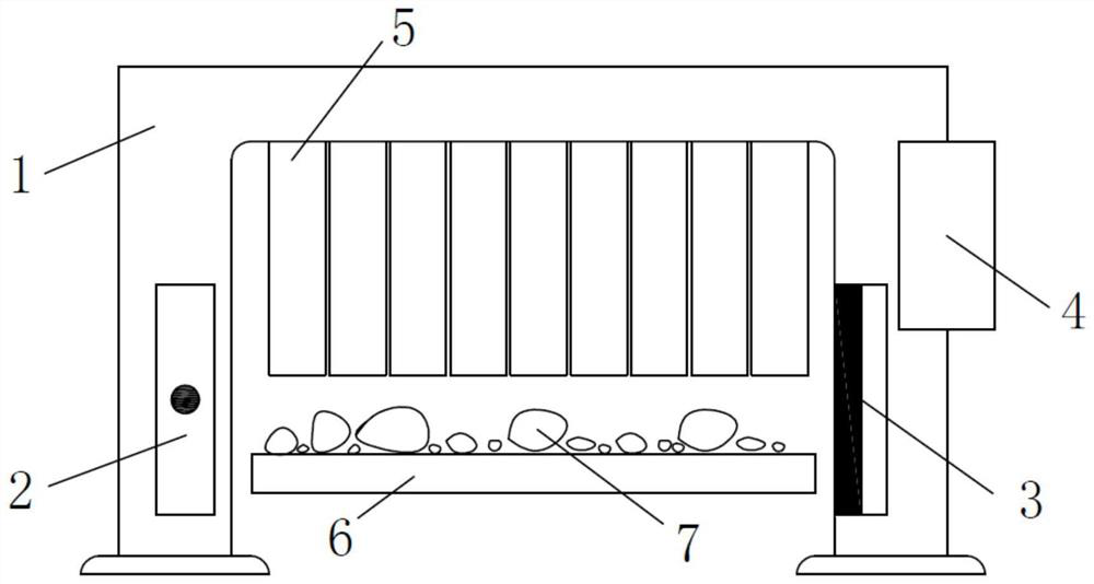
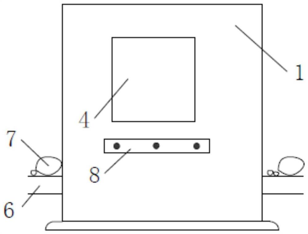
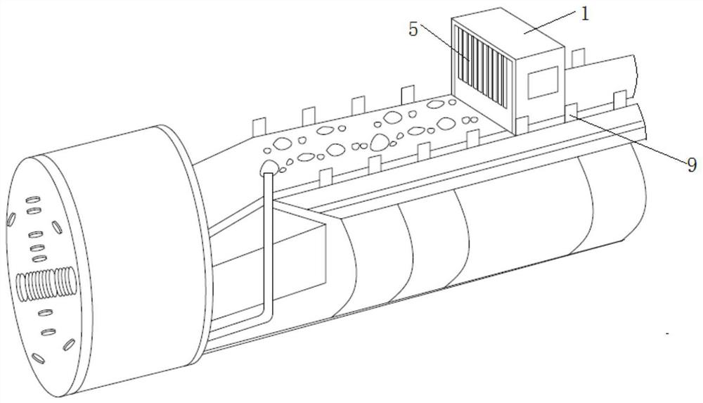
[0044] In a typical embodiment of the present invention, such as Figure 1-Figure 3 As shown, a TBM rock slag ray transmission imaging CT real-time scanning imaging device includes a housing, an X-ray emission source 2, a detector 3, a controller connected to an imaging screen 4, and the housing is a radiation-proof and dust-proof housing 1. Wherein the anti-radiation and dust-proof casing 1 is a door frame type, and is arranged across the TBM conveyor 6, so that the TBM conveyor 6 (belt conveyor) passes through the radiation-proof and dust-proof casing 1 to transport rock slag 7, and the radiation-proof and dust-proof casing 1 is The metal material is used to protect the internal mechanical parts and prevent radiation. It is coated with an anti-corrosion and anti-rust coating, and the X-ray emission source 2 and the detector 3 are respectively arranged in the center of the two side walls of the radiation-proof and dust-proof shell, that is, in the Both sides of the TBM convey...

Embodiment 2

[0056] A method for using a TBM slag ray transmission imaging CT real-time scanning imaging device, comprising the following contents:

[0057] A TBM rock slag ray transmission imaging CT real-time scanning imaging device is fixed above the TBM conveyor, and the TBM conveyor conveys the rock slag;

[0058] Turn on the X-ray emission source, the X-rays penetrate the slag, and the density of the slag area is proportional to the absorption capacity of the X-ray;

[0059] The detector receives X-rays and transmits signals to the controller, and the controller obtains imaging results. When X-rays penetrate rock slag, the area with higher slag density has a stronger ability to absorb rays, which will be characterized after scanning The data of density distribution is intuitively reflected in the picture as the change of color brightness. The lowest density is black, and the highest density is white. The image obtained by this is also a density distribution map;

[0060] The control...


PUM

PropertyMeasurementUnit
thicknessaaaaaaaaaa

Abstract

The invention discloses a TBM (tunnel boring machine) rock slag ray transmission imaging CT real-time scanning and imaging device and method, the problem that a camera in the prior art cannot acquirethe internal information of the rock slag is solved, and the following benefit is achieved that the rock slag can be scanned in real time, so that the TBM operation parameters can be timely adjusted.According to the scheme, the TBM rock slag ray transmission imaging CT real-time scanning and imaging device comprises a shell, an X-ray emission source, a detector and a controller; the shell can bearranged across a TBM conveyor, and the inner part and two side surfaces of the shell are of hollow structures; the X-ray emission source is arranged on the inner side of the shell; the detector is arranged on the inner side of the shell and is opposite to the X-ray emission source; the controller is respectively independently connected with the X-ray emission source and the detector, the X-ray emission source is used for emitting X-rays, rocks conveyed by the TBM conveyor have diverse densities, and the detector is used for receiving the X-rays and transmitting signals to the controller.

Description

technical field [0001] The invention relates to the field of geotechnical engineering, in particular to a CT real-time scanning imaging device and method for ray transmission imaging of TBM rock slag. Background technique [0002] With the large-scale construction of my country's infrastructure and the progress of the western development, there will be a large number of long tunnels to be built in the construction of railways, highways, large and medium-sized hydropower stations, South-to-North Water Diversion, West-East Gas Transmission and other projects; The conditions are complex, and the requirements for construction speed, environmental protection, quality and benefit are high, and the full-section tunnel boring machine (TBM) has the advantages of fast excavation, high quality, safety, economy, environmental protection and reduced labor intensity. Therefore, TBM is widely used It is used in the construction of deep buried long tunnels in our country. Of all the componen...

Claims


Application Information

Patent Timeline
Patent Type & Authority Patents(China)
IPC IPC(8): G01N23/046
CPCG01N23/046
Inventor 刘斌王亚旭王瑞睿郭旭高博洋朱颜赵光祖
Owner 山东百廿慧通工程科技有限公司
Learn More