
A Design Method for Electromagnetic Compatibility of Low-light Image Intensifier

A low-light image intensifier, electromagnetic compatibility technology, applied in the direction of eliminating unnecessary electromagnetic effects, circuits, discharge tubes, etc., can solve the problems of excessive test, small shell size, and unusable volume.

Active Publication Date: 2021-04-27
NORTH NIGHT VISION TECH
View PDF9 Cites 0 Cited by
  • Summary
  • Abstract
  • Description
  • Claims
  • Application Information

AI Technical Summary

Problems solved by technology

[0006] The image intensifier adopts a thin-walled, light-weight, insulated and high-voltage-resistant plastic shell, which has no electromagnetic shielding effect, and the shell cannot be connected to the input ground or the earth. It is easy to interfere with external radiation and cause the RE102 test to exceed the standard; it is also easily affected by external radiation, resulting in the RS103 test. exception occurs when
[0007] The high-voltage power supply of the image intensifier contains multiple DC-DC switching power supplies, which will inevitably generate electromagnetic interference with rich frequencies. Due to the small size of the shell, it is impossible to use large-scale filter components such as capacitors and inductors, resulting in the presence of switches on the input line. Frequency fundamental wave interference and high-order harmonic conduction interference and radiation cause CE102 and RE102 tests to exceed the standard

Method used


Image

  • A Design Method for Electromagnetic Compatibility of Low-light Image Intensifier
  • A Design Method for Electromagnetic Compatibility of Low-light Image Intensifier
  • A Design Method for Electromagnetic Compatibility of Low-light Image Intensifier

Examples


Embodiment

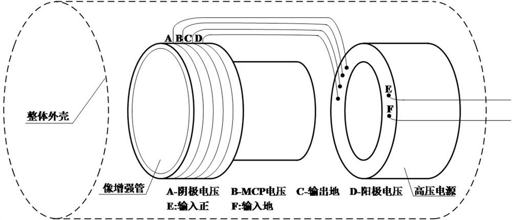
[0077] as attached figure 1 As shown, the low-light image intensifier is composed of a high-voltage power supply, an image intensifier tube, interconnection leads and a whole shell. The high-voltage power supply is a ring structure with a separate shell, and the lead wires include cathode voltage leads, MCP (micro channel plate) voltage leads, output ground leads, anode voltage leads, input positive leads and input ground leads; the image intensifier tube is a vacuum device , interconnected with the power supply through high-voltage insulated leads; the high-voltage power supply and the image intensifier tube are encapsulated and sealed in the overall casing.

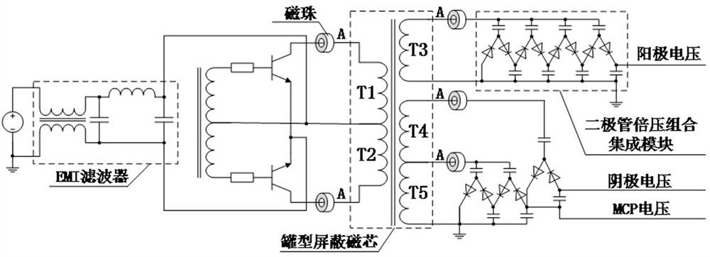
[0078] as attached figure 2 As shown, the high-voltage power supply includes three functional units such as the input terminal, the transformer winding and the output terminal. The A terminal of the transformer winding T1~T5 is the switching node, and the dv / dt and di / dt at the node are relatively large, and due to th...


PUM


Abstract

The invention discloses an electromagnetic compatibility design method for a low-light image intensifier, which solves the problem of the volume of the existing low-light image intensifier by performing electromagnetic compatibility design on the high-voltage power supply, the image intensifier tube, and the overall shell that make up the low-light image intensifier. The contradiction between the weight limit and electromagnetic compatibility improves the anti-interference ability of the low-light image intensifier in the environment of strong electromagnetic interference, and improves its working stability.

Description

technical field [0001] The invention relates to the technical field of image intensifiers, in particular to an electromagnetic compatibility design method for low-light image intensifiers. Background technique [0002] The low-light image intensifier is the core device of the low-light night vision device. The main factor affecting its working stability in the traditional battlefield is the intensity of incident light, which requires it to be able to adapt to 10 -4 lx~10 4 lx has an even wider lighting range, and can image clearly in strong flash environments such as gunfire. With the development of automatic gating high-voltage power supply technology, the dynamic range and service life of the image intensifier have been greatly improved, and the problem of imaging under strong light has been solved. [0003] The use of various reconnaissance, detection, and communication equipment in modern high-tech warfare leads to a very complex electromagnetic environment on the batt...

Claims


Application Information

Patent Timeline
Patent Type & Authority Patents(China)
IPC IPC(8): H01J31/50H01J29/00
CPCH01J29/003H01J31/503
Inventor 杜培德李晓露曾进能苏天宁周盛涛李亚情朱文锦杨可洁
Owner NORTH NIGHT VISION TECH
Learn More