Rear pull rotary crossing-over frame

A cross-frame, rotating technology, applied in the direction of overhead lines/cable equipment, etc., can solve the problems of increased workload of construction personnel, unstable power output process, long construction time, etc., to avoid repeated adjustment work, stable recovery process, The effect of convenient construction

Active Publication Date: 2019-10-08
CHINA ELECTRIC POWER RES INST +3
View PDF10 Cites 0 Cited by
  • Summary
  • Abstract
  • Description
  • Claims
  • Application Information

AI Technical Summary

Problems solved by technology

[0002] With the rapid development of my country's transmission line construction, the country is paying more and more attention to the safety of construction. In the construction of existing transmission lines, cross-stretching construction has the characteristics of many dangerous points and complex construction environment.
At present, the method of setting up spanning frames is generally used to protect the objects to be spanned. Although the construction units design the lattice spanning frame to span the construction, although the basic functional requirements of spanning are met, there are some problems at the same time, such as large structural mass, complicated installation, structural Unstable and inconvenient for construction; hard-sealed net poles need to be installed separately during installation, the construction time is long and the process is complicated; and it is prone to distortion during the implementation process, which not only increases the workload of construction personnel, but also is not safe enough; insufficient power And the power output process is not stable, prone to jamming

Method used


Image

  • Rear pull rotary crossing-over frame
  • Rear pull rotary crossing-over frame
  • Rear pull rotary crossing-over frame

Examples


Embodiment Construction

[0024] In order to better understand the present invention, the content of the present invention will be further described below in conjunction with the accompanying drawings and examples.

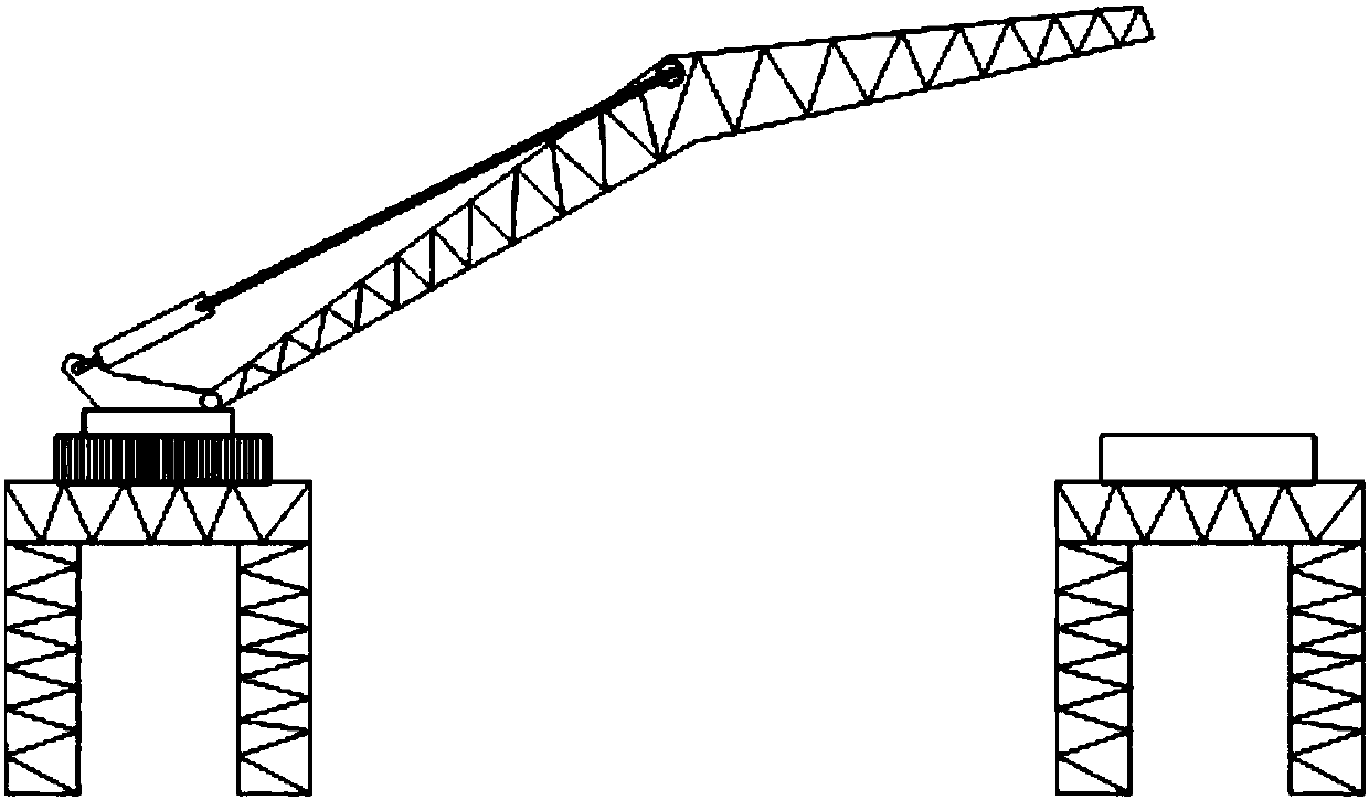
[0025] Such as figure 1 As shown, it is a schematic diagram of overlapping of the back-pull rotating span frame provided by the present invention. In the initial installation state, the back-pull hydraulic cylinder 3 is used to raise the net-sealing arm 4 along the direction of the object to be spanned, and the rotating platform 2 is rotated to the spanning direction, and then the back-pull hydraulic cylinder 3 is used to adjust the raising of the net-sealing arm 4 The angle is overlapped to the support platform 6 on the opposite side. The installation process is realized through the rotating platform and the back-pull hydraulic cylinder, which avoids the way of docking on both sides, prevents uneven docking, and ensures the sealing time.

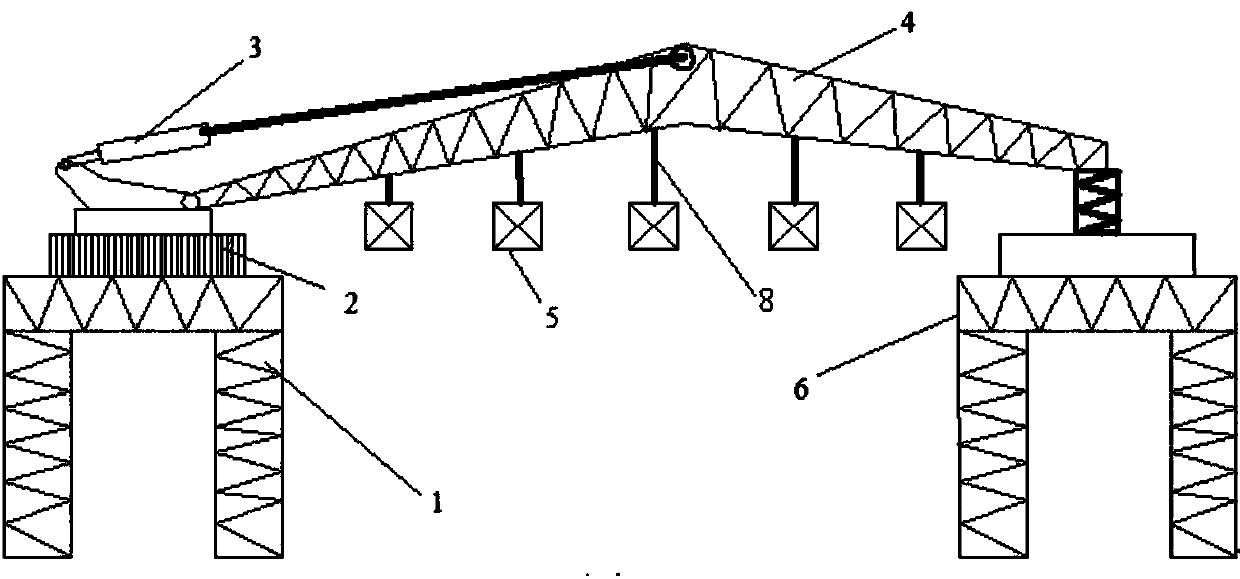
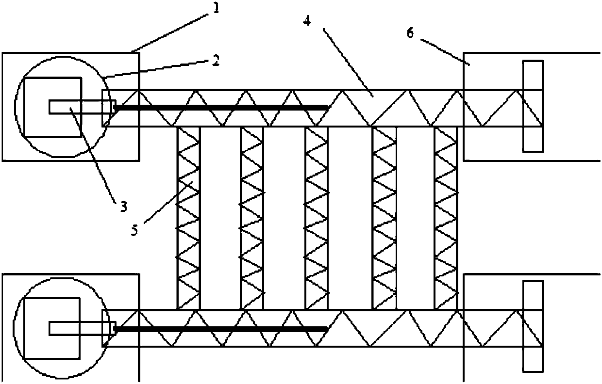
[0026] Such as Figure 2~3 As shown, it is a sc...


PUM


Abstract

The invention discloses a rear pull rotary crossing-over frame, which comprises a worktable, a rotating mechanism disposed on the worktable, a rear pull hydraulic mechanism disposed on the rotating mechanism and a support table, wherein the rotating mechanism comprises a rotating platform; the rear pull hydraulic mechanism comprises a rear pull hydraulic cylinder disposed on the rotating platformand an inverted V-shaped network closing arm connected with the rear pull hydraulic cylinder; and the support table is disposed at a free end of the network closing arm. During the installation process, the action is stable and reliable, a jamming phenomenon is not easy to occur, and the structure is stable and reliable; the construction workload is saved, the network closing time is shortened andthe engineering cost is reduced; the repeated adjustment of the two sides during the construction process is prevented; the network closing speed is fast, the mechanical failure rate is low, the network closing time is guaranteed, the network closing boom adopts a lattice structure, the structure is stable, and network closing protection is carried out through a hard network closing holding pole,in comparison with the traditional soft network closing, the advantages of strong impact resistance, high safety, high reliability and the like can be achieved.

Description

Technical field: [0001] The invention relates to a transmission line construction equipment, in particular to a spanning frame device used in transmission line spanning construction. Background technique: [0002] With the rapid development of transmission line construction in our country, the country pays more and more attention to the safety of construction. However, in the construction of existing transmission lines, crossing construction has the characteristics of many dangerous points and complex construction environment. At present, the method of setting up spanning frames is generally used to protect the objects to be spanned. Although the construction units design the lattice spanning frame to span the construction, although the basic functional requirements of spanning are met, there are some problems at the same time, such as large structural mass, complicated installation, structural Unstable and inconvenient for construction; hard-sealed net poles need to be inst...

Claims


Application Information

Patent Timeline
Patent Type & Authority Applications(China)
IPC IPC(8): H02G1/02
CPCH02G1/02
Inventor 夏拥军万建成蔡松林胡院生罗义华姚兰波李金光贾宁
Owner CHINA ELECTRIC POWER RES INST
Why Eureka
Try Eureka