Laser device and tissue characterizing method

A laser equipment and laser technology, applied in the use of spectral diagnosis, medical science, surgery, etc., can solve problems such as time-consuming and troublesome, and achieve the effect of avoiding secondary intervention and rapid identification.

Active Publication Date: 2019-10-08
ADVANCED OSTEOTOMY TOOLS - AOT
View PDF17 Cites 4 Cited by
  • Summary
  • Abstract
  • Description
  • Claims
  • Application Information

AI Technical Summary

Problems solved by technology

Indeed, and despite recent technological advances, biopsy remains a time-consuming and rather cumbersome procedure

Method used


Image

  • Laser device and tissue characterizing method
  • Laser device and tissue characterizing method
  • Laser device and tissue characterizing method

Examples


Embodiment Construction

[0086] In the following description, certain terms are used for convenience and are not intended to limit the present invention. The terms "right", "left", "upper", "lower", "below" and "above" refer to directions in the drawings. The term includes the terms explicitly mentioned as well as their derivatives and terms with similar meanings. Additionally, spatially relative terms such as "below," "beneath," "lower," "above," "upper," "proximal," "distal," etc. may be used to describe The relationship of one element or feature to another element or feature. These spatially relative terms are intended to encompass different positions and orientations of the device in use or operation in addition to the positions and orientations shown in the figures. For example, if the device in the figures is turned over, elements described as "below" or "beneath" other elements or features would then be oriented "above" or "above" the other elements or features. Thus, the exemplary term "bel...


PUM


Abstract

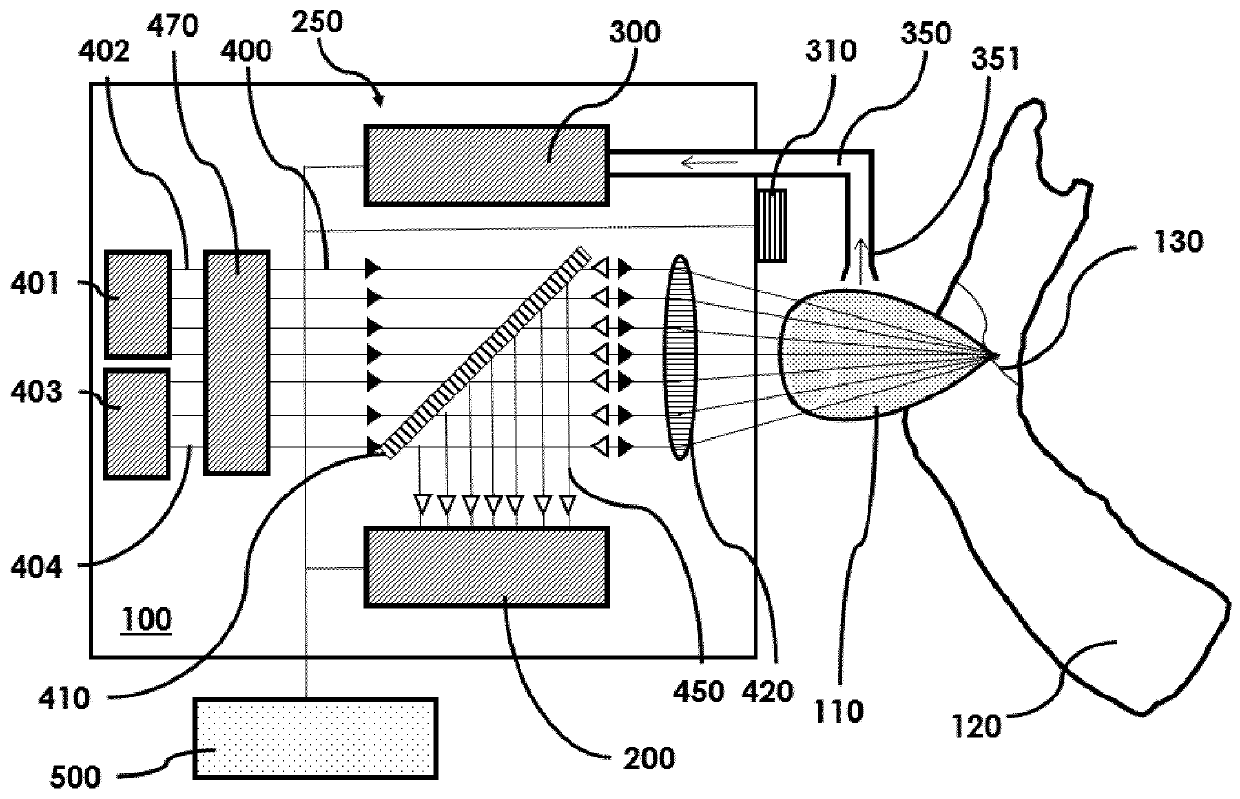
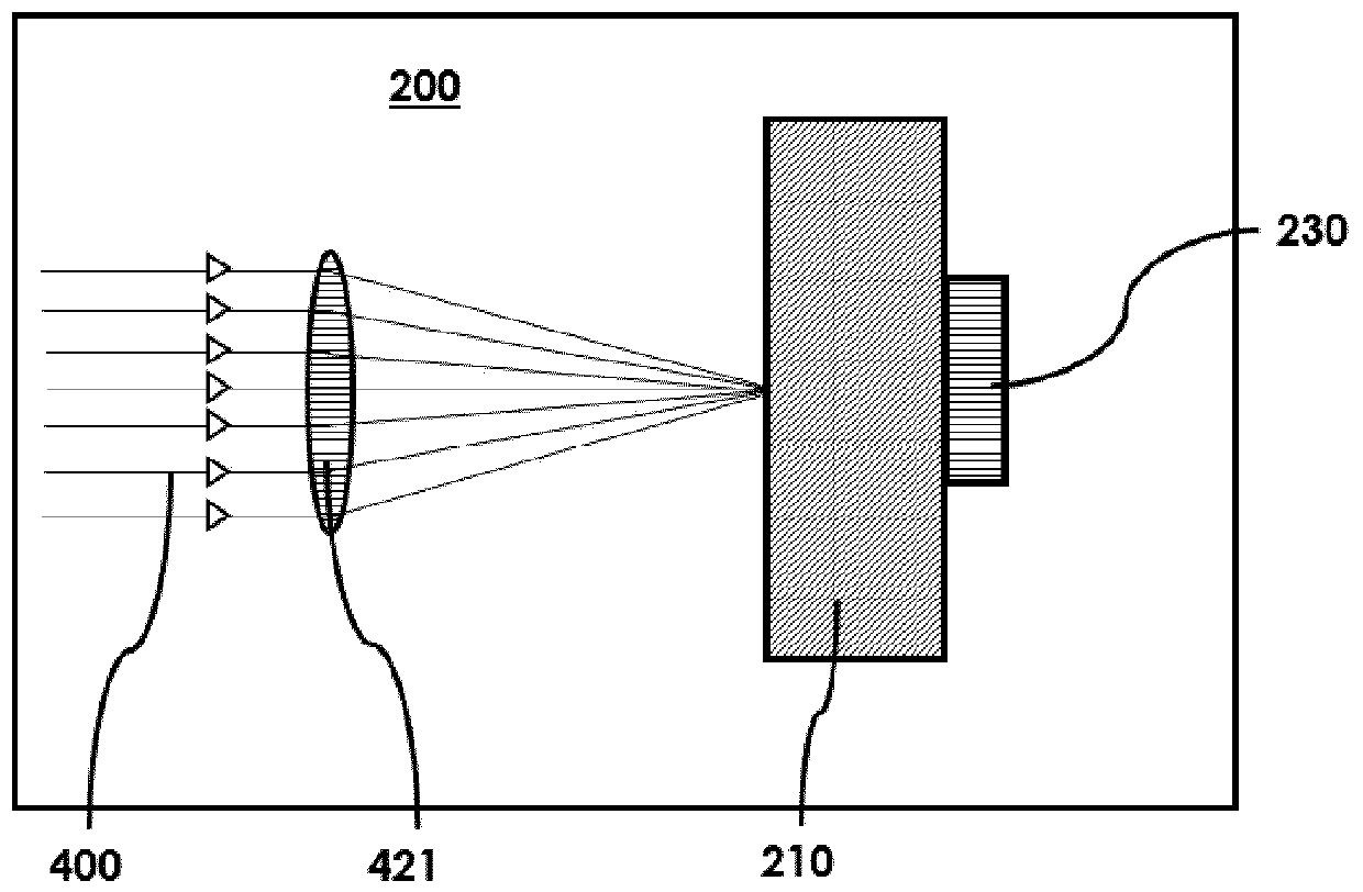
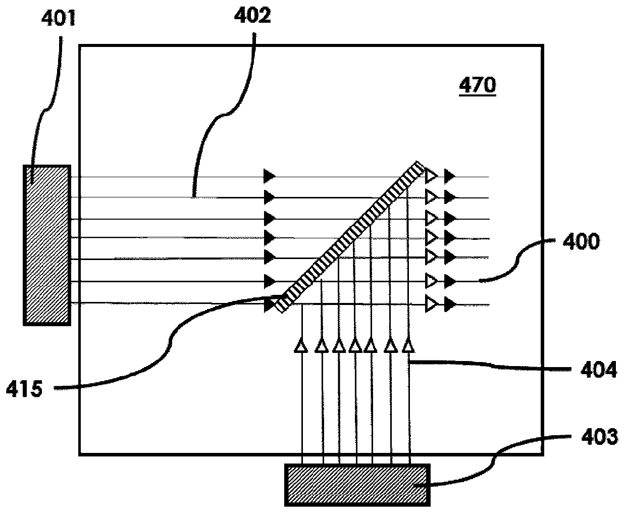
A laser device (100) has an ablation laser source (401) adapted to provide an ablating laser beam (402; 402i) for ablating a target tissue (120). It further comprises a plume analyzing arrangement (250) adapted to identify and / or quantify substances in the debris of the plume (110) generated by the ablating laser beam (402) ablating the target tissue (120) particularly substances being biomarkersof the ablated target tissue (120).

Description

technical field [0001] The invention relates to a laser device according to the preamble of independent claim 1, and more particularly to a method of tissue characterization. [0002] Such a laser device comprising an ablative laser source adapted to provide an ablative laser beam for ablating target tissue may be used in many applications, for example in medical or surgical applications where natural human or animal tissue is to be cut or ablated. Background technique [0003] For cutting and drilling hard or soft human or animal tissue (eg bone, cartilage, etc.), various tools have long been used, such as saws, chisels or drills. Cutting and drilling with laser beams has also grown in popularity in recent years. For example, in some computer assisted surgical procedures it is known to use a laser beam as a cutting instrument. More specifically, for example, in WO 2011 / 035792 A1, a computer-aided and robot-guided laser osteotomy medical device is described which allows pr...

Claims


Application Information

Patent Timeline
Patent Type & Authority Applications(China)
IPC IPC(8): A61B18/20A61B18/00
CPCA61B18/203A61B2018/00642A61B2018/00702A61B18/20A61B5/0075A61B2018/00577A61B2018/00565A61B2018/2253A61B2018/20361A61B2018/20359A61B2018/2283A61B2018/00982A61B2017/00061A61B2218/008
Inventor A·E·布鲁诺K·O·伯恩森
Owner ADVANCED OSTEOTOMY TOOLS - AOT
Why Eureka
Try Eureka