Efficient wet and dry dual-purpose draught fan

A dry and wet dual-purpose fan technology, which is applied in mechanical equipment, machines/engines, liquid fuel engines, etc., can solve the problems of low maximum efficiency, low efficiency of dry and wet dual-purpose fans, poor diversion and pressure diffusion effects, etc., to achieve The effect of converting air kinetic energy into pressure energy is sufficient

Pending Publication Date: 2019-10-11
CINDERSON TECH (SUZHOU) CO LTD
View PDF0 Cites 3 Cited by
  • Summary
  • Abstract
  • Description
  • Claims
  • Application Information

AI Technical Summary

Problems solved by technology

like figure 1 As shown, the existing wet and dry fans are generally installed with a windshield 12 on the side of the motor end cover 11 close to the moving impeller 13, and the windshield 12 has side openings to vent the wind. This kind of dry and wet fan is simple to manufacture, but Only rely on the inner end surface of the windshield 12 and the end surface of the end cover 11 to conduct flow diversion. There is a connected circumferential annular flow diversion space between the windshield 12 and the air outlet of the moving impeller 13, and the effect of diversion and pressure diffusion is poor, which causes the vacuum cleaner to dry The efficiency of dual-purpose fans is generally low, and the maximum efficiency is less than 47%

Method used


Image

  • Efficient wet and dry dual-purpose draught fan
  • Efficient wet and dry dual-purpose draught fan
  • Efficient wet and dry dual-purpose draught fan

Examples


Embodiment Construction

[0031] The following will clearly and completely describe the technical solutions in the embodiments of the present invention with reference to the accompanying drawings in the embodiments of the present invention. Obviously, the described embodiments are only some, not all, embodiments of the present invention. Based on the embodiments of the present invention, all other embodiments obtained by persons of ordinary skill in the art without creative efforts fall within the protection scope of the present invention.

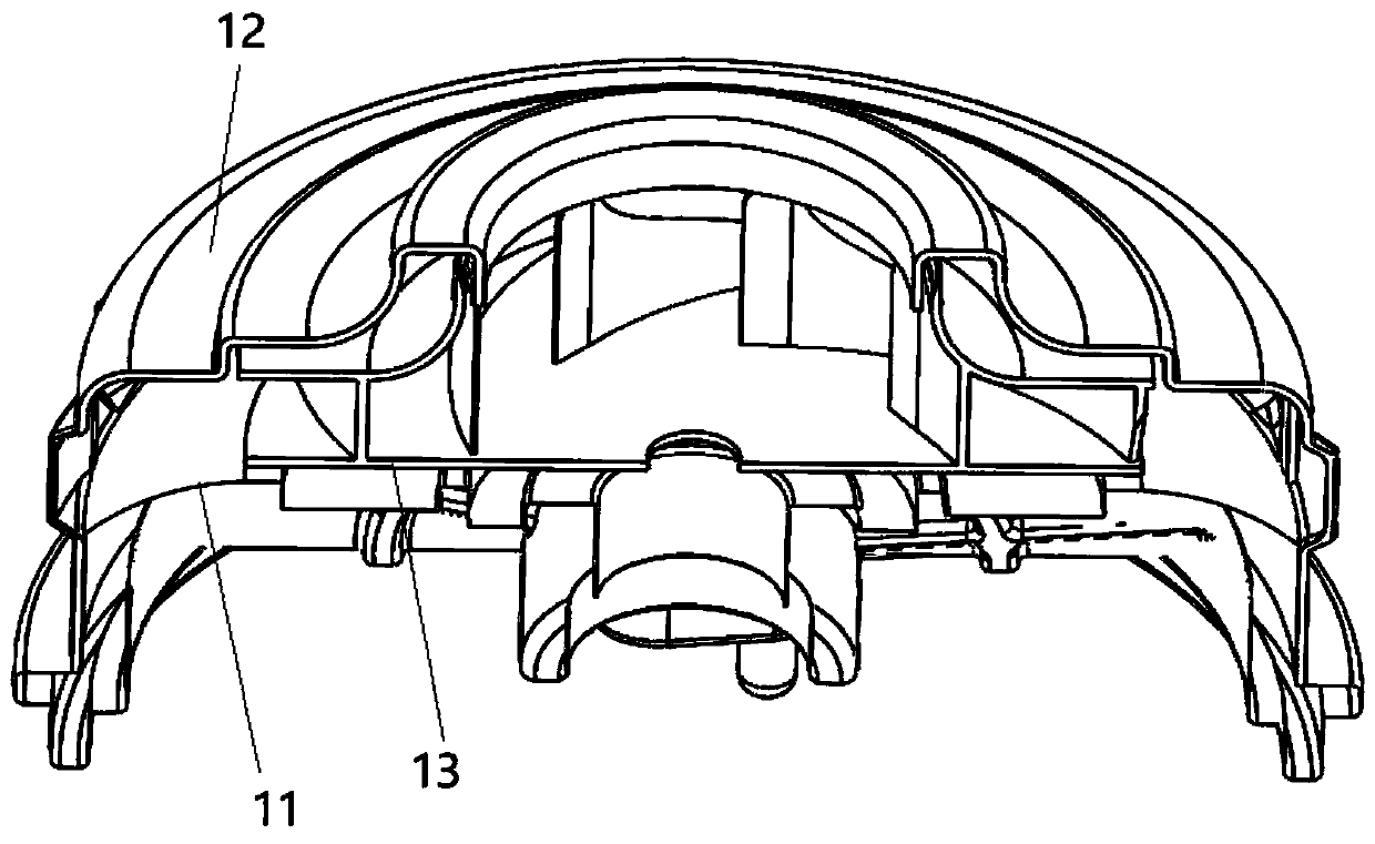
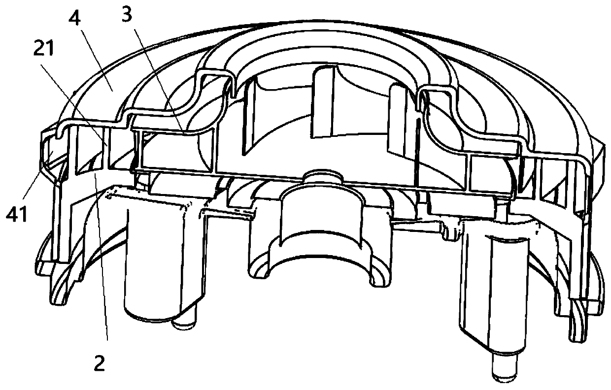
[0032] Such as figure 2 As shown, a high-efficiency wet and dry fan includes a motor, a moving impeller 3 and a windshield 4, and the motor includes a casing (not shown), a stator (not shown), a rotor (not shown) and an end cover 2. The stator and rotor are arranged in the installation cavity formed by the casing and the end cover 2, and the rotor has a rotating shaft protruding from the end cover; the moving impeller 3 is installed on the end face side of the end...


PUM


Abstract

The invention provides an efficient wet and dry dual-purpose draught fan which comprises a motor, a movable impeller and a wind cover, wherein the motor comprises a case, a stator, a rotor and an endcover; a plurality of pressure-diffusion sheets are arranged on the end face of the movable impeller side of the end cover, extend to the inner side wall of the side part of pressure-diffusion holes of the wind cover in a single arc shape from the air outlet of the outer circumference of the movable impeller, and are spirally and radially distributed; and a plurality of independent pressure-diffusion flow guiding air flues are formed between the air outlet of the movable impeller and the pressure-diffusion holes of the wind cover through combination of the end cover, the wind cover and the pressure-diffusion sheet. Compared with the prior art, guiding and pressure diffusion of the airflow at the outlet of the movable impeller are realized through the pressure-diffusion sheets; matching pressure-diffusion holes are formed in the tail part, corresponding to the pressure-diffusion sheets, of the wind cover; the side wall at the pressure-diffusion holes of the wind cover is tightly connected with the outlets of the pressure-diffusion sheets to realize two-level flow guiding and pressure diffusion of the efficient wet and dry dual-purpose draught fan, conversion of the airflow kinetic energy into pressure energy is more sufficient, and the pneumatic performance of high hydrostatic pressure efficiency is realized.

Description

technical field [0001] The invention relates to the technical field of vacuum cleaner motors, in particular to a high-efficiency wet and dry fan. Background technique [0002] Wet and dry fans can be used not only in dry environments, but also in humid and water-less conditions, and are widely used in various wet and dry vacuum cleaners. Such as figure 1 As shown, the existing wet and dry fans are generally installed with a windshield 12 on the side of the motor end cover 11 close to the moving impeller 13, and the windshield 12 has side openings to vent the wind. This kind of dry and wet fan is simple to manufacture, but Only rely on the inner end surface of the windshield 12 and the end surface of the end cover 11 to conduct flow diversion. There is a connected circumferential annular flow diversion space between the windshield 12 and the air outlet of the moving impeller 13, and the effect of diversion and pressure diffusion is poor, which causes the vacuum cleaner to dr...

Claims


Application Information

Patent Timeline
Patent Type & Authority Applications(China)
IPC IPC(8): F04D25/08F04D29/30F04D29/44F04D29/66
CPCF04D25/08F04D29/30F04D29/444F04D29/667
Inventor 朱云舫
Owner CINDERSON TECH (SUZHOU) CO LTD
Why Eureka
Try Eureka