Method and device for collecting heat dissipation water vapor at top of thermal power plant circulating water cooling tower

A cooling tower, circulating water technology, applied in water shower coolers, heat exchange equipment, heat exchanger types, etc., can solve problems such as water waste, save industrial water, reduce consumption, and improve reuse rate. Effect

Pending Publication Date: 2018-02-09
阳城国际发电有限责任公司 +1
View PDF0 Cites 1 Cited by
  • Summary
  • Abstract
  • Description
  • Claims
  • Application Information

AI Technical Summary

Problems solved by technology

[0003] In the various processes of thermal power plants, there are usually a lot of mist clusters released in the air at the top of the cooling tower, resulting in a wa

Method used


Image

  • Method and device for collecting heat dissipation water vapor at top of thermal power plant circulating water cooling tower
  • Method and device for collecting heat dissipation water vapor at top of thermal power plant circulating water cooling tower
  • Method and device for collecting heat dissipation water vapor at top of thermal power plant circulating water cooling tower

Examples


no. 1 example

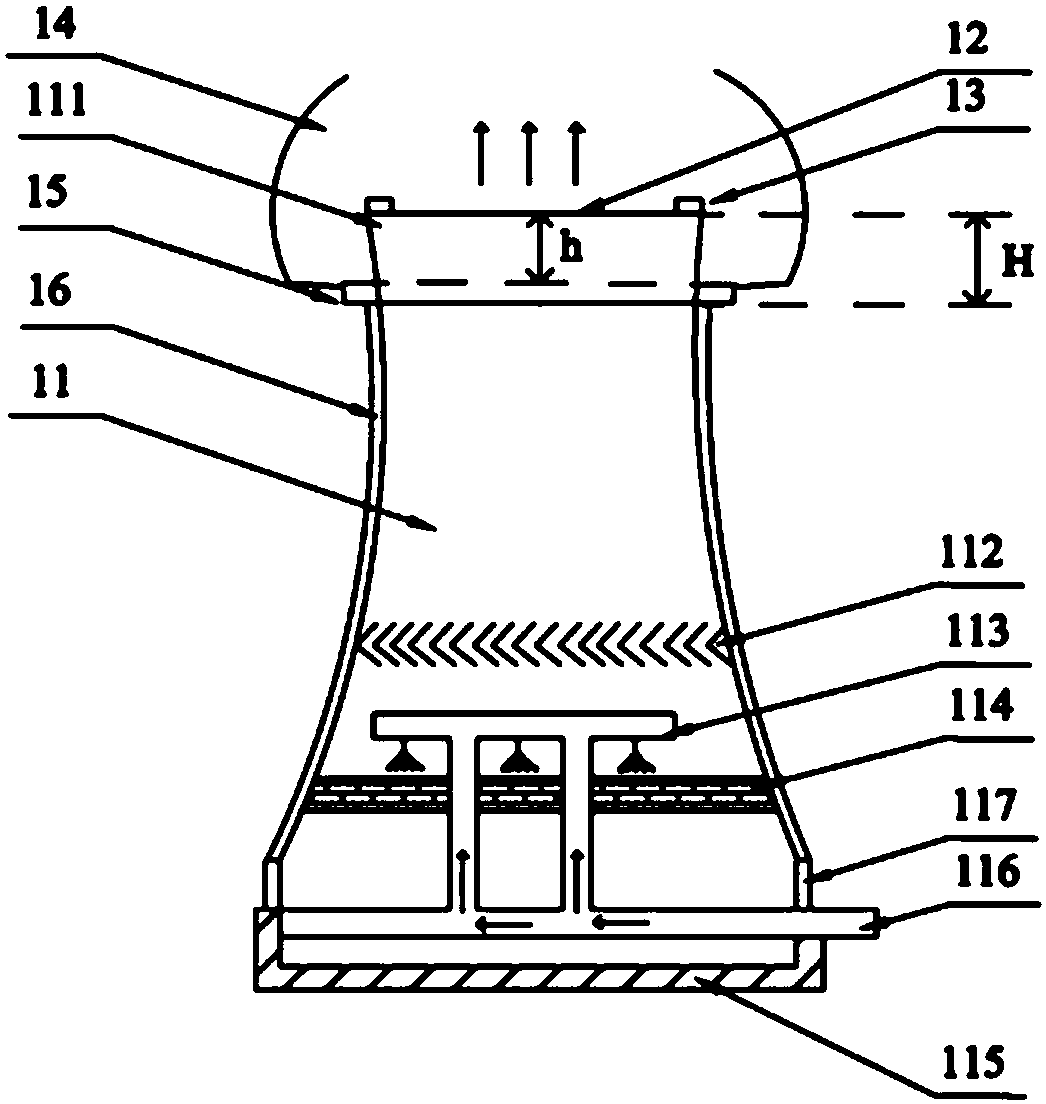
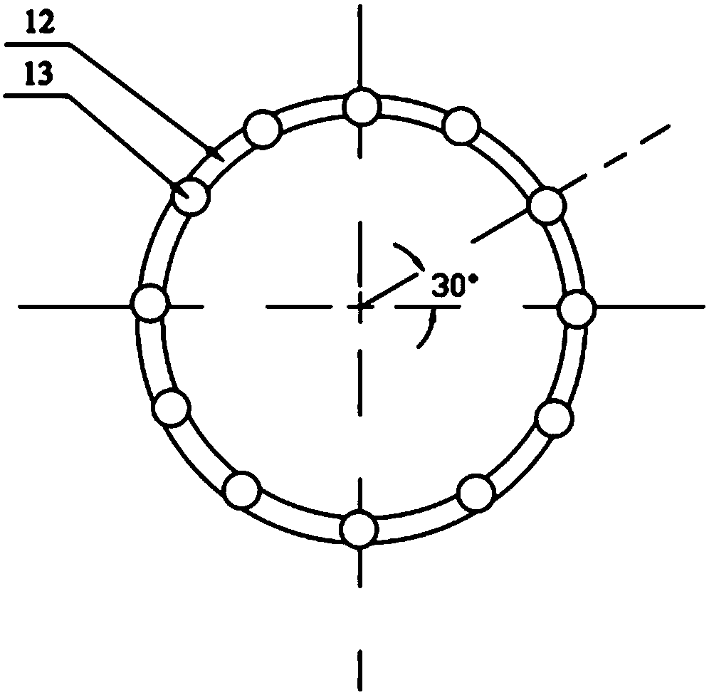
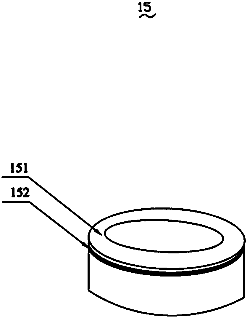
[0026] In the first embodiment of the present invention, a device for collecting heat dissipation water vapor at the top of a thermal power plant circulating water cooling tower includes a collection cover 14, a diversion groove 15, four drain pipes 16, a rigid ring 12 and a plurality of axial flow fans 13. The collection cover 14 is an annular cover body, its annular side is in a certain radian, and it is located at the top of the cooling tower. The guide groove 15 is an annular body, which surrounds the upper part of the cooling tower and is located at the bottom of the collection cover 14 and is integrated with it. The four drain pipes 16 are located on the side wall of the cooling tower, and one end of each drain pipe 16 is communicated with the diversion groove 15, and the other end is connected with the cold water pool 115. The height of the upper surface of the diversion groove 15 from the tower top 111 is h, and the height of the lower surface of the diversion groove 15...

no. 2 example

[0030] In the second embodiment of the present invention, a method 2 of collecting heat dissipation water vapor at the top of a thermal power plant circulating water cooling tower (for the structure mentioned in the following steps, please refer to the view and numbering of the device provided in the first embodiment of the present invention) comprises the following steps:

[0031] Step S1: Install the rigid ring 12, the axial flow fan 13, the collection cover 14, the diversion groove 15 and the drain pipe 16 on the top of the cooling tower 11. During installation, according to the temperature sensor and the pressure sensor at the top 111 of the cooling tower 11 According to the heat dissipation and load-bearing conditions, the axial fan 13 with different powers is selected.

[0032] Step S2: Sensing the local perennial wind direction, wind force, temperature and humidity of the cooling tower 11 and sending the signal to the CPU to adjust the shape of the collection cover 14 it...


PUM


Abstract

A device for collecting heat dissipation water vapor at the top of a thermal power plant circulating water cooling tower is disclosed. The cooling tower is a hyperbolic cooling tower, a cold water pool is arranged at the bottom of the cooling tower, the cold water pool comprises a collecting cover, a flow guiding trough, four drainage pipes, a rigid ring and a plurality of axial flow fans, the collecting cover is an annular cover body, the annular side face of the collecting cover is in a certain radian, the collecting cover is located at the top of the cooling tower, and the flow guiding trough is an annular trough; and the annular body surrounds the upper portion of the cooling tower and is located at the bottom of the collecting cover to be integrally connected with the collecting cover, the four drainage pipes are located on the side wall of the cooling tower, one end of each drainage pipe communicates with the flow guiding trough, and the other end of each drainage pipe is connected with the cold water pool. A method for collecting the heat dissipation water vapor at the top of the thermal power plant circulating water cooling tower by using the device comprises four steps, the device and the method can effectively collect the heat dissipation water vapor at the top of the cooling tower, the repeated water-using rate of the thermal power plant is increased, the consumptionamount of the thermal power plant circulating cooling water is reduced, and a decisive effect on water saving of the thermal power plant is achieved.

Description

technical field [0001] The invention belongs to the technical field of water treatment in thermal power plants, and in particular relates to a method and a device for collecting heat-dissipating water vapor at the top of a circulating water cooling tower of a thermal power plant. Background technique [0002] In recent years, my country is a country with very poor water resources, especially in inland water-scarce areas, water resources have become the main factor restricting its economic development. Thermal power plants are large water consumers. A 6×350MW thermal power plant consumes about 8×10⁴m3 of water per day, which is equivalent to the daily domestic water consumption of residents in a small and medium-sized city. The shortage of water resources will limit the operation of thermal power plants. It may even affect the development of other industries or sectors. [0003] In the various processes of thermal power plants, there are usually a lot of mist clusters releas...

Claims


Application Information

Patent Timeline
IPC IPC(8): F28C1/00F28F25/04F28F25/12F28F25/00F28F27/00
CPCF28C1/00F28F25/00F28F25/04F28F25/12F28F27/003
Inventor 乔永成刘林虎常旭东王艳阳姜英彪邸若冰宋金峰杨晓伟秦栋肖伟华侯保灯焦阔
Owner 阳城国际发电有限责任公司
Why Eureka
Try Eureka