An impeller for a forward centrifugal fan

A technology of centrifugal fans and impellers, which is applied to parts of pumping devices for elastic fluids, mechanical equipment, machines/engines, etc., which can solve the difficulties in processing and installing semi-conical impellers, the performance degradation of conical impeller fans, and the impact on fans. Efficiency and noise problems, to achieve the effect of weakening the shedding phenomenon, reducing the number of blades and improving efficiency

Active Publication Date: 2020-09-18
NINGBO FOTILE KITCHEN WARE CO LTD
View PDF22 Cites 0 Cited by
  • Summary
  • Abstract
  • Description
  • Claims
  • Application Information

AI Technical Summary

Problems solved by technology

[0004] Therefore, the working capacity of the front and rear discs of the traditional equal-chord impeller is unbalanced along the axial direction, resulting in serious boundary layer separation on the blade surface, which in turn affects the efficiency and noise of the fan.
[0005] There are mainly two existing solutions: one is to obliquely cut the leading edge of the blade near the front disk, which significantly improves the unevenness of the flow field at the fan inlet, but this method is mainly used in multi-blade centrifugal fans. The cutting is based on the base of the impeller, without redesigning the flow channel and blade profile, so the effect of performance improvement is limited; the other is based on the flow characteristics of the front disk of the impeller, using a semi-conical impeller to prevent the flow of the leading edge And the secondary flow of the volute has a certain impact, but the processing and installation of the semi-conical impeller is difficult. Under the same size frame, that is, when the installation space is limited, the performance of the fan corresponding to the conical impeller decreases.

Method used


Image

  • An impeller for a forward centrifugal fan
  • An impeller for a forward centrifugal fan
  • An impeller for a forward centrifugal fan

Examples


Embodiment Construction

[0020] The present invention will be further described in detail below in conjunction with the accompanying drawings and embodiments.

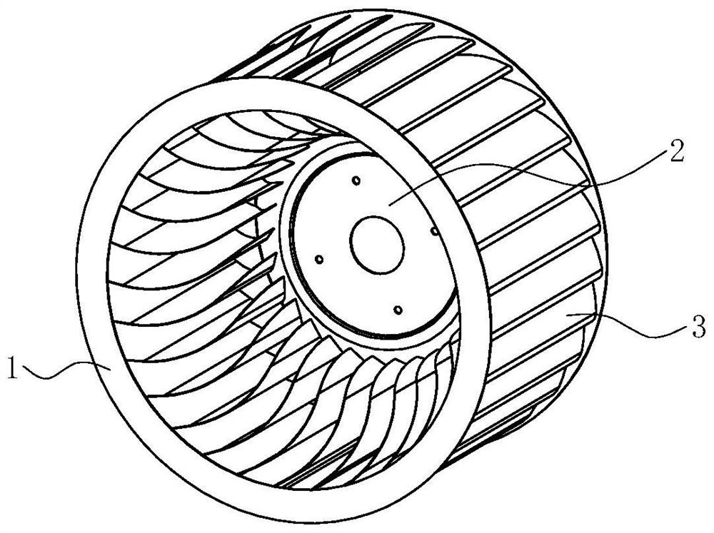
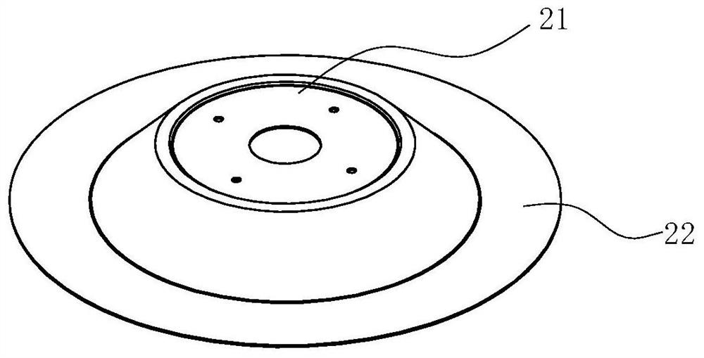
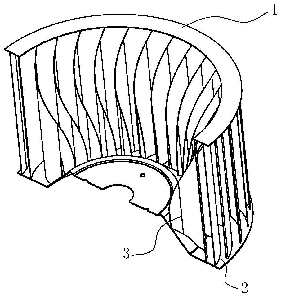
[0021] see figure 1 with figure 2 , an impeller for a forward centrifugal fan, including a front disk 1, a rear disk 2, and a plurality of blades 3 arranged between the front disk 1 and the rear disk 2, and each blade 3 is evenly arranged in the circumferential direction. The centrifugal fan can be a fan used in ventilating equipment such as range hoods and heating, ventilating and air-conditioning. The front disc 1 is in the shape of a ring, and the rear disc 2 includes an inner boss 21 and a ring 22 located on the outer periphery of the boss 21. The boss 21 is in the shape of a circular platform and is used for installing a motor for driving the impeller to rotate. The front disc 1 and the rear disc 2 respectively adopt a mechanical connection structure with the blade 3 . The projection of the axis of the impeller 3 on the axial directio...


PUM


Abstract

The invention discloses an impeller for a forward centrifugal fan. The impeller comprises a front disc, a rear disc and a plurality of blades arranged between the front disc and the rear disc, the chord length at the position, close to the front disc, of each blade is smaller than the chord length at the position, close to the rear disc, of each blade, a projection of an axis of a impeller in theaxial direction is a central point, and the impeller is characterized in that the change rule of the chord lengths at different shaft sections in the axial direction of the impeller is a gradual change spline curve. Compared with the prior art, the impeller has the advantages that through the design of the variable-chord length blades, the chord length of the front disc is reduced, the chord length of the rear disc is increased, so that the air inlet capacity of the front disc is increased, the phenomenon of flow separation in a blade channel near the front disc is weakened, the purpose of increasing the air exhaust capacity of a middle disc and the rear disc is realized, the problem of the nonuniform working capability of the front disc and the rear disc is solved, the efficiency is improved, and the noise is reduced.

Description

technical field [0001] The invention relates to a power device, in particular to an impeller of a forward centrifugal fan. Background technique [0002] The multi-blade centrifugal fan is the main power system of range hoods and other ventilation equipment. It has the characteristics of compact structure, low noise, high pressure coefficient and large flow coefficient. The energy conversion of the fan mainly depends on the work done by the impeller, so the performance of the impeller directly affects the characteristics and noise of the range hood. The cross-section of the blade shaft of the traditional multi-blade centrifugal fan is mostly circular arc and equal chord length blades, which have the characteristics of large number of blades, large blade curvature, narrow blade path, and short flow path. [0003] The forward multi-blade centrifugal fan is a kind of fan with axial air intake, the gas flows into the fan along the axial direction, and is discharged radially afte...

Claims


Application Information

Patent Timeline
Patent Type & Authority Patents(China)
IPC IPC(8): F04D29/28F04D29/30F04D29/66
CPCF04D29/281F04D29/30F04D29/666
Inventor 杨伟刚
Owner NINGBO FOTILE KITCHEN WARE CO LTD
Why Eureka
Try Eureka