Lamp holder enabling bulb convenient to change

A lamp holder and light bulb technology, applied in the field of lighting, can solve the problems of insufficiency, demand, and large load-bearing capacity.

Inactive Publication Date: 2019-10-11
国网河南省电力公司镇平县供电公司
View PDF6 Cites 0 Cited by
  • Summary
  • Abstract
  • Description
  • Claims
  • Application Information

AI Technical Summary

Problems solved by technology

However, the structure of the present invention is relatively complicated, and there is a greater demand for load-bearing capacity. In addition, it cannot meet the needs of users who have less requirements for brightness, that is, only a single light bulb can solve the problem.

Method used


Image

  • Lamp holder enabling bulb convenient to change
  • Lamp holder enabling bulb convenient to change
  • Lamp holder enabling bulb convenient to change

Examples


Embodiment 1

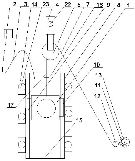
[0037] Such as figure 1 , 2 3. As shown in 3, a lamp holder for easy replacement of light bulbs includes a lamp holder body 1, and a transmission line 3 for electrical connection between an indoor power source 2 and the lamp holder body 1. The lamp holder for easy replacement of light bulbs also includes Auxiliary agency

[0038] The auxiliary mechanism includes a pulling module arranged on the upper part of the lamp holder body 1 and a sliding module arranged on the back of the lamp holder body 1;

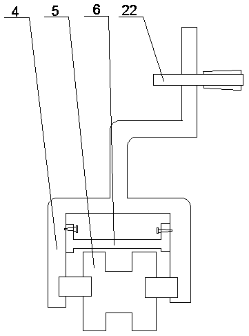
[0039] The traction module includes a fixing clip 4 arranged on the wall, a pulley 5 arranged in the fixing clip, a protective plate 6 arranged on the upper end of the fixing clip 4, a protective plate 6 arranged on the pulley 5 and connected to the upper end of the lamp holder body 1. The first traction rope 7, a fixing unit arranged on the wall and used for fixing the lower end of the first traction rope 7;

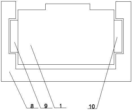
[0040] The sliding module includes a sliding groove 8 arranged on the wall, ...

Embodiment 2

[0054] Such as Figure 4 As shown, the difference between this embodiment and the first embodiment is that the fixing unit includes a fixing ring 18 and a tail clip 19 arranged on the fixing ring 18.

[0055] Part of the length of the first traction rope 7 can be wound on the fixing ring 18, and the buckle ring 11 can be clamped and fixed by the long tail clamp 19, so as to realize the fixing of the end of the first traction rope 7 away from the lamp holder body 1 .

Embodiment 3

[0057] Such as Figure 5 As shown, the difference between this embodiment and the second embodiment is that the bottom of the lamp holder body 1 is also provided with a second traction rope 20.

[0058] The arrangement of the second traction rope 20 enables the lamp holder body 1 to obtain additional downward traction in addition to being subjected to gravity, so as to better move downwards and overcome the first slip. Block 9 or the possible jamming phenomenon between the second sliding block 10 and the sliding groove 8;

[0059] The end of the second traction rope 20 away from the lamp holder body 1 can be fixed by means of a tail clamp 19.

[0060] In addition, when an upward traction force is applied to the lamp holder body 1 through the first traction rope 7, a downward traction force can be applied to the lamp holder body 1 through the second traction rope 20 at the same time, so as to slow down the lamp holder. The upward movement speed of the main body 1 makes the movement s...


PUM


Abstract

The invention provides a lamp holder enabling a bulb convenient to change. The lamp holder comprises a lamp holder body and a power transmission line, wherein the power transmission line is used for achieving electric connection between an indoor power supply and the lamp holder body. The lamp holder enabling the bulb convenient to change further comprises an auxiliary mechanism. The auxiliary mechanism comprises a traction module and a sliding module, wherein the traction module is arranged on the upper portion of the lamp holder body, and the sliding module is arranged on the back of the lamp holder body. The traction module comprises a fixing clamp arranged on a wall, a pulley arranged in the fixing clamp, a protection plate arranged at the lower end of the fixing clamp, a first traction rope and a fixing unit, wherein the first traction rope is arranged on the pulley and connected with the upper end of the lamp holder body, and the fixing unit is arranged on the wall and used for fixing the lower end of the first traction rope. The sliding module comprises a sliding groove formed in the wall, a first sliding block arranged at the left end of the lamp holder body and a second sliding block arranged at the right end of the lamp holder body. By means of the lamp holder, a user no so high also can conveniently change the bulb without a tool such as a ladder or a chair or help of other people.

Description

Technical field [0001] The present invention relates to the field of lighting technology, in particular to a lamp holder that is convenient for replacing bulbs. Background technique [0002] With the laying of power lines and the emergence of various light bulbs, the dark environment can no longer continue to cause major restrictions and impacts on people's production and life. [0003] In people’s daily life, in order to meet the needs of lighting and safety of electricity, the lamp holder is usually fixed on a wall at a certain height from the ground, but when the bulb fails and needs to be removed for inspection or replacement, a ladder is often needed. Or a chair touches the light bulb, and the process of climbing up and down on a ladder or chair is not very safe. If you are not careful, you may get a fall accident, and the process of moving a ladder is not easy and labor-saving, which can meet the high demand Chairs are not available in everyone's home. [0004] In order to re...

Claims


Application Information

Patent Timeline
Patent Type & Authority Applications(China)
IPC IPC(8): F21V21/20F21V21/38F21V19/04
CPCF21V19/04F21V21/20F21V21/38
Inventor 王林玉姜斌斌丁熙安
Owner 国网河南省电力公司镇平县供电公司
Why Eureka
Try Eureka