Active load reducing device for sudden load of aero-engine tester

An aero-engine and active load reduction technology, which is applied in the field of aero-engines, can solve problems such as the inability to meet the needs of fan blade fly-off load vibration reduction and load reduction, and achieve good economy, low cost, and good repeatability.

Active Publication Date: 2019-10-11
NORTHWESTERN POLYTECHNICAL UNIV
View PDF10 Cites 0 Cited by
  • Summary
  • Abstract
  • Description
  • Claims
  • Application Information

AI Technical Summary

Problems solved by technology

[0005] In order to overcome the deficiencies in the prior art that cannot meet the needs of the fan blade flying off load, vibration reduction and load redu

Method used


Image

  • Active load reducing device for sudden load of aero-engine tester
  • Active load reducing device for sudden load of aero-engine tester
  • Active load reducing device for sudden load of aero-engine tester

Examples


Example Embodiment

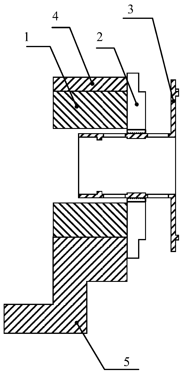
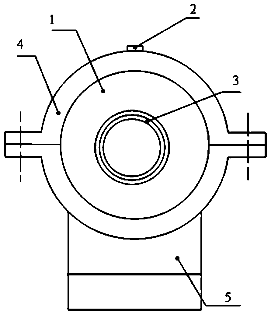
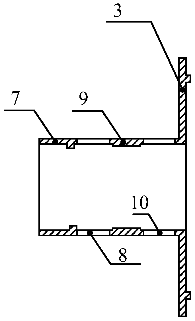
[0032] This embodiment is an active load-reducing device for an aero-engine experimenter after sudden loading, including a pneumatic chuck 1 , chuck jaws 2 , variable stiffness elastic support 3 , collar 4 and chuck support 5 . Wherein: the pneumatic chuck 1 is placed on the upper surface of the chuck support 5 and fixed by the collar 4 . The working sleeve at one end of the variable stiffness elastic support 3 is loaded into the inner surface of the pneumatic chuck, and the flange at the other end of the variable stiffness elastic support is connected with the simulated experimenter.

[0033] The pneumatic chuck 1 is a hollow rotary body. The inner diameter of the pneumatic chuck is 5-10 mm larger than the outer diameter of the working section of the variable stiffness elastic support 3 . There is a three-jaw chuck on one end face of the pneumatic chuck, and the three-jaw chuck adopts the prior art. The pneumatic chuck 1 is electrically controlled: when the power is on, the...


PUM


Abstract

The invention discloses an active load reducing device for a sudden load of an aero-engine tester. According to the device, a pneumatic chuck is fixed on the upper surface of a chuck support; a working sleeve at one end of a variable stiffness elastic support is arranged in the inner surface of the pneumatic chuck; a flange at the other end of the variable stiffness elastic support is connected with a simulation tester; a three-jaw chuck at one end face of the pneumatic chuck is in a clamping state when the three-jaw chuck is powered on and is in a release state when the three-jaw chuck is powered off; and the variable rigidity elastic support is clamped by adjusting the distance between chuck jaws. The device disclosed by the invention has the beneficial effects that by utilizing the variable stiffness elastic support, the support stiffness is adaptively changed and the critical rotation speed of a rotor system is significantly changed, thereby reducing an impact load of a blade flying off the rotor system and providing experimental support for the safety design of the rotor system when a sudden imbalance occurs; and the device has the characteristics of low cost, good repeatability and implementation convenience.

Description

technical field [0001] The invention relates to the field of aeroengines, in particular to the safety design of a turbofan engine with a large bypass ratio. Background technique [0002] As the blades of modern high-bypass turbofan engines become larger and larger, once the fan blades fall off (FanBlade Off) in the engine, there will be a sudden increase in imbalance, which will seriously affect the normal operation of the engine and cause a major threat to personnel and property , causing incalculable consequences to the flight safety of the aircraft. According to China's airworthiness safety requirements, the engine must be able to accommodate damaged parts and run for at least 15 seconds without igniting, and the installation joints will not fail. The US Federal Aviation Administration and the European Aviation Safety Agency have similar requirements. GJB / Z 101-97 clearly requires that when the blades fly out at the maximum allowable steady-state speed, the engine shall...

Claims


Application Information

Patent Timeline
IPC IPC(8): G01M15/02G01M15/14
CPCG01M15/02G01M15/14
Inventor 侯理臻廖明夫王四季
Owner NORTHWESTERN POLYTECHNICAL UNIV
Why Eureka
Try Eureka