Method for improving effective coverage of sound field of ultrasonic probe, and ultrasonic detection wedge block

An ultrasonic probe, ultrasonic testing technology, applied in the analysis of solids using sonic/ultrasonic/infrasonic waves, material analysis using sonic/ultrasonic/infrasonic waves, and measuring devices, etc. , the detection process is cumbersome and other problems, to achieve the effect of increasing the effective coverage, improving the consistency, and being easy to use

Pending Publication Date: 2019-10-11
HUST WUXI RES INST
View PDF0 Cites 2 Cited by
  • Summary
  • Abstract
  • Description
  • Claims
  • Application Information

AI Technical Summary

Problems solved by technology

The effective coverage of the sound field of the probe is related to the shape, size and other factors of the piezoelectric chip. For an ultrasonic probe with fixed parameters, it is difficult to increase the effective coverage of the sound field.
[0004] In addition, in the existing ultrasonic flaw detection equipment, it is usually necessary to place the ultrasonic straight probe obliquely to complete the oblique incidence of ultrasonic waves, and it is necessary to design an auxiliary structure to assist its inclination, the mechanical structure is complex, and the detection process is cumbersome.

Method used


Image

  • Method for improving effective coverage of sound field of ultrasonic probe, and ultrasonic detection wedge block
  • Method for improving effective coverage of sound field of ultrasonic probe, and ultrasonic detection wedge block
  • Method for improving effective coverage of sound field of ultrasonic probe, and ultrasonic detection wedge block

Examples


Embodiment Construction

[0039] The present invention will be further described below in conjunction with specific drawings and embodiments.

[0040] The present invention proposes a method for improving the effective coverage of the ultrasonic probe sound field, including:

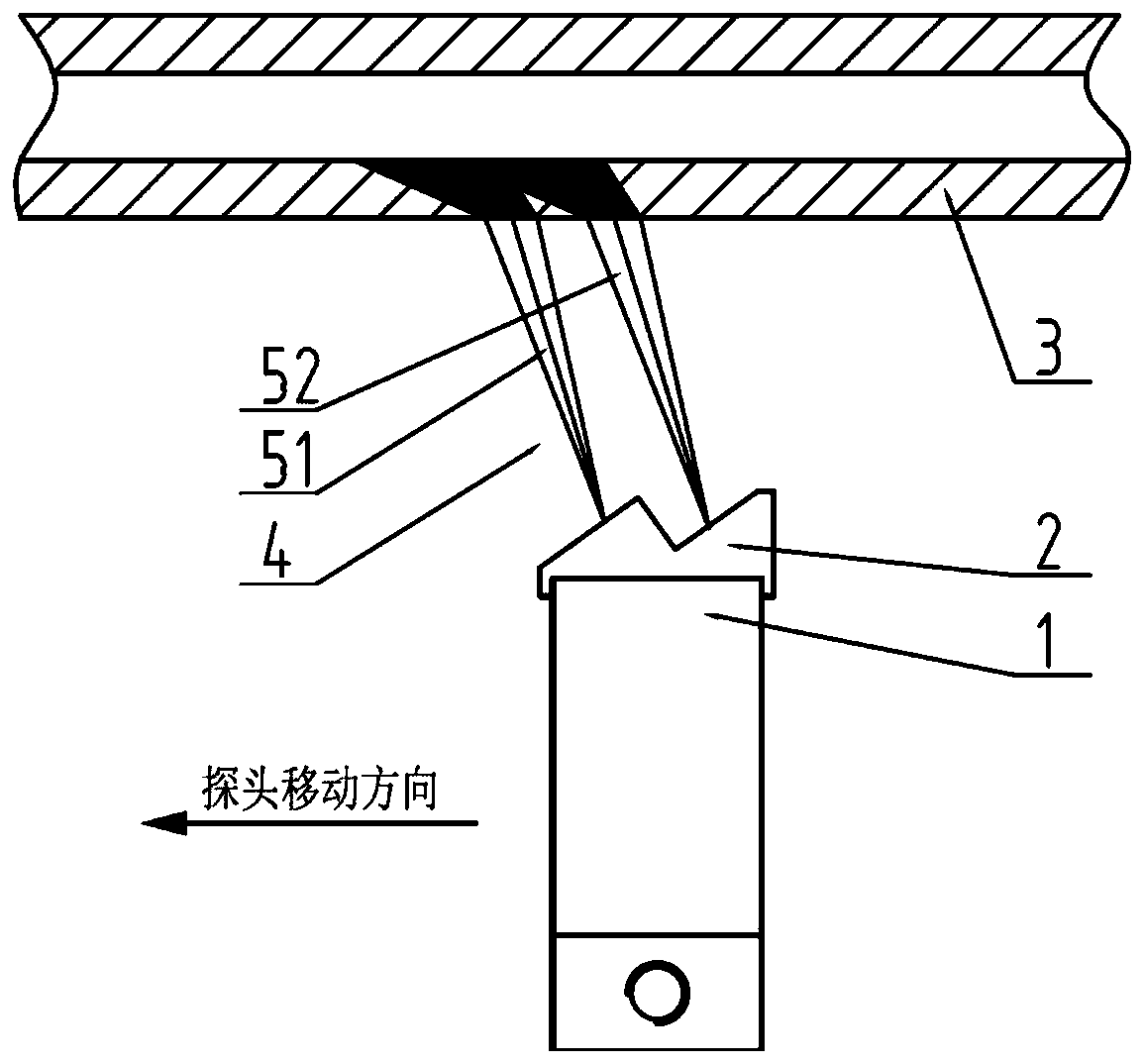
[0041] Step S1, determining the parameters of the ultrasonic testing wedge at least according to the structural size of the ultrasonic probe and the material of the coupling agent, and the ultrasonic testing wedge is attached to the ultrasonic probe;

[0042] Step S2, using the ultrasonic detection wedge to divide the ultrasonic waves emitted by the ultrasonic probe into sound beams to form multiple sound beams, and simultaneously detect the workpiece;

[0043] Step S3, the ultrasonic probe and the ultrasonic detection wedge move laterally relative to the workpiece, and the ultrasonic probe receives echo signals to detect defects inside the workpiece;

[0044] In some embodiments of the present invention, the multiple acoustic b...


PUM


Abstract

The invention provides an ultrasonic detection wedge block, comprising a working surface and a connecting surface on front and back sides, wherein the shape of the working surface of the ultrasonic detection wedge block comprises one or more jagged steps, a rising surface of each step is a focusing surface or plane, and a falling surface is a plane; the rising surface of the step is obliquely arranged, so that the direction of a sound beam emitted by an ultrasonic probe can be changed, and oblique incidence of ultrasonic waves can be achieved on a workpiece; and the plurality of jagged steps can divide a single sound beam emitted by the ultrasonic probe into several sound beams. The invention further provides a method for improving the effective coverage of a sound field of the ultrasonicprobe, wherein the ultrasonic detection wedge block is attached above the ultrasonic probe; and the sound beam of the ultrasonic wave emitted by the ultrasonic probe is divided by the ultrasonic detection wedge block to form a plurality of sound beams, and meanwhile the workpiece is detected. By adopting the method provided by the invention, the effective coverage of the sound field of the ultrasonic probe can be increased, and the consistency of detection signals is improved.

Description

technical field [0001] The invention relates to the field of ultrasonic flaw detection, in particular to a method for increasing the effective coverage of an ultrasonic probe sound field and an ultrasonic detection wedge. Background technique [0002] In ultrasonic nondestructive testing, the consistency of testing signals is one of the most important indicators of testing equipment. During automatic detection, the detection ability of each ultrasonic probe for the same defect is different due to reasons such as spatial position and probe performance, resulting in inconsistent energy of the detection signal, and the energy of the detection signal directly reflects the size information of the defect, and the inconsistency of the detection signal Will directly affect the assessment of defects. Therefore, it is very important to improve the signal consistency of the testing equipment, which can improve the performance of the equipment to a higher level. In automatic ultrasonic...

Claims


Application Information

Patent Timeline
Patent Type & Authority Applications(China)
IPC IPC(8): G01N29/04G01N29/22G01N29/24
CPCG01N29/043G01N29/221G01N29/2437
Inventor 康宜华刘瑞
Owner HUST WUXI RES INST
Why Eureka
Try Eureka