Quasi-orthogonal optical wedge adjustment mechanism

An adjustment mechanism, quasi-orthogonal technology, applied in optics, optical components, installation and other directions, can solve the problems of complex structure, high assembly accuracy requirements, intolerant of shock and vibration, etc., to achieve easy use, small size, and improved adjustment accuracy Effect

Pending Publication Date: 2019-10-11
NO 60 RES INST OF GENERAL STAFF DEPT PLA
View PDF0 Cites 4 Cited by
  • Summary
  • Abstract
  • Description
  • Claims
  • Application Information

AI Technical Summary

Problems solved by technology

[0003] The existing optical axis adjustment device in the laser transmitter is a two-dimensional mechanical adjustment device that can adjust the direction of the laser beam. It adjusts the optical axis of the laser beam in the horizontal and vertical directions. This method cannot take into account the accuracy and volume, and the structure is complex. High requirements and not resistant to shock and vibration

Method used


Image

  • Quasi-orthogonal optical wedge adjustment mechanism
  • Quasi-orthogonal optical wedge adjustment mechanism
  • Quasi-orthogonal optical wedge adjustment mechanism

Examples


Embodiment

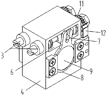
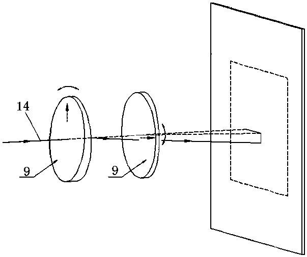
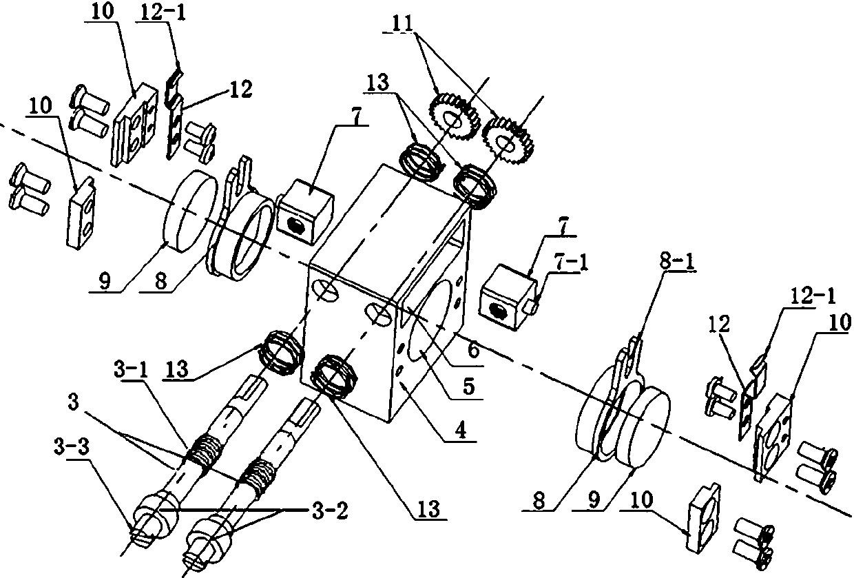
[0040] When the quasi-orthogonal optical wedge adjustment mechanism is in use, it has a hollow equipment box 1, a laser transmitter 2 is fixedly installed at the rear end of the equipment box 1, and a quasi-orthogonal optical wedge adjustment mechanism is fixedly installed in front of the laser transmitter 2; On the equipment box 1, there is a light channel through hole at the position directly in front of the quasi-orthogonal optical wedge adjustment mechanism, and the optical axis 14 used for the laser transmitter 2 to emit laser light is emitted after the position is adjusted by the quasi-orthogonal optical wedge adjustment mechanism. ; One side of the equipment box 1 is provided with two through holes of equal size, which are used for the top of the adjustment screw 3 on the quasi-orthogonal optical wedge adjustment mechanism to protrude for easy adjustment.

[0041] On the outer wall of the equipment box 1, a scale is provided on the edge of the adjusting screw 3 for conve...


PUM


Abstract

The invention discloses a quasi-orthogonal optical wedge adjustment mechanism and relates to equipment for adjusting laser optical axis direction, specifically a device for adjusting an optical axis through utilization of an optical wedge. The quasi-orthogonal optical wedge adjustment mechanism is equipped with an optical wedge base. Two sets of mutually matching optical wedge adjustment units aremounted at two sides of the optical wedge base. An optical channel which penetrates the optical wedge base is set between the optical wedge adjustment units. An optical wedge adjustment slot which penetrates the optical wedge base is set above the optical channel. Each optical wedge adjustment unit comprises an adjustment screw, a slide block and an optical wedge ring. Threads are set in a middlesection of the adjustment screw. Two ends of the adjustment screw are mirror surfaces. A limiting boss is set at a head part of the adjustment screw. A diameter of the limiting boss is greater than that of a through hole on a side face of an equipment box and is used for limiting with an inner wall of the equipment box. An adjustment knob is set at a top end of the limiting boss. The adjustment knob is smaller than the through hole on the side face of the equipment box, so the adjustment knob can extend to an outer wall of the equipment box. The diameter of the second half section of the adjustment screw is smaller than that of the middle section. The optical wedge ring is annular. An optical wedge is embedded into the ring.

Description

technical field [0001] The invention relates to a quasi-orthogonal optical wedge adjustment mechanism, which relates to a device for adjusting the direction of the optical axis of a laser, in particular a device for adjusting the optical axis by using an optical wedge. Background technique [0002] In laser shooting training, the laser transmitter is installed on the gun barrel and gun barrel. Before use, the optical axis of the transmitter's laser beam must be calibrated with the aiming point using the transmitter's optical axis adjustment device before it can be used normally. [0003] The existing optical axis adjustment device in the laser transmitter is a two-dimensional mechanical adjustment device that can adjust the direction of the laser beam. It adjusts the optical axis of the laser beam in the horizontal and vertical directions. This method cannot take into account the accuracy and volume, and the structure is complex. High requirements, and not resistant to shock...

Claims


Application Information

Patent Timeline
Patent Type & Authority Applications(China)
IPC IPC(8): G02B7/00
CPCG02B7/004
Inventor 孙华权薛汝东吕战强吴泽楷郑冠华谢宇宙
Owner NO 60 RES INST OF GENERAL STAFF DEPT PLA
Why Eureka
Try Eureka