
Chain for vacuum conveyor

A conveyor and vacuum technology, applied in conveyors, transportation and packaging, etc., can solve the problems of insufficient adsorption force, small adsorption area, and difficult application, so as to reduce pressure drop, improve durability, and prevent pressure drop Effect

Active Publication Date: 2019-10-11
DAIDO KOGYO CO LTD
View PDF10 Cites 0 Cited by
  • Summary
  • Abstract
  • Description
  • Claims
  • Application Information

AI Technical Summary

Problems solved by technology

[0007] In the technology of Patent Document 1, the suction hole formed in the flat link (flat body) is composed of linear through holes of the same diameter from the front surface (placement surface) to the back surface (suction box side), If it is a row of empty plastic bottles, sufficient adsorption force can be obtained, but especially in the case of transporting multiple rows of objects to be conveyed and heavy objects such as cans, sufficient adsorption force cannot be obtained due to the small adsorption area. Adsorption force, there is a concern that it cannot be transported stably
[0008] Since the technique of Patent Document 2 targets a row of empty plastic bottles, it is used for a certain wide chain that can arrange multiple rows of conveyed objects and for a vacuum conveyor in a can making process. chain case, it is difficult to apply

Method used


Image

  • Chain for vacuum conveyor
  • Chain for vacuum conveyor
  • Chain for vacuum conveyor

Examples


Embodiment Construction

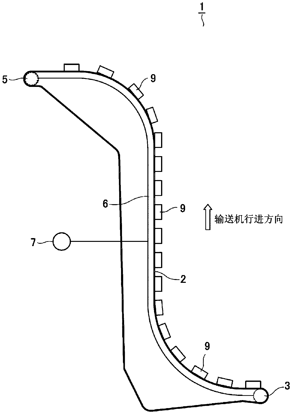
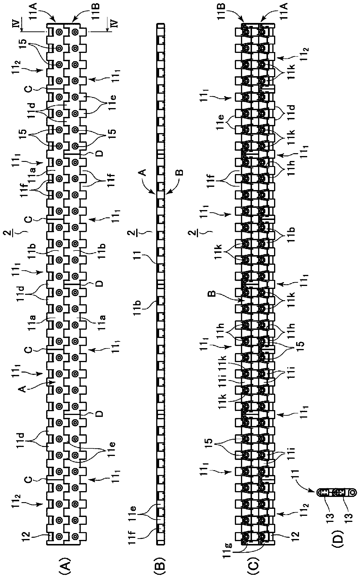
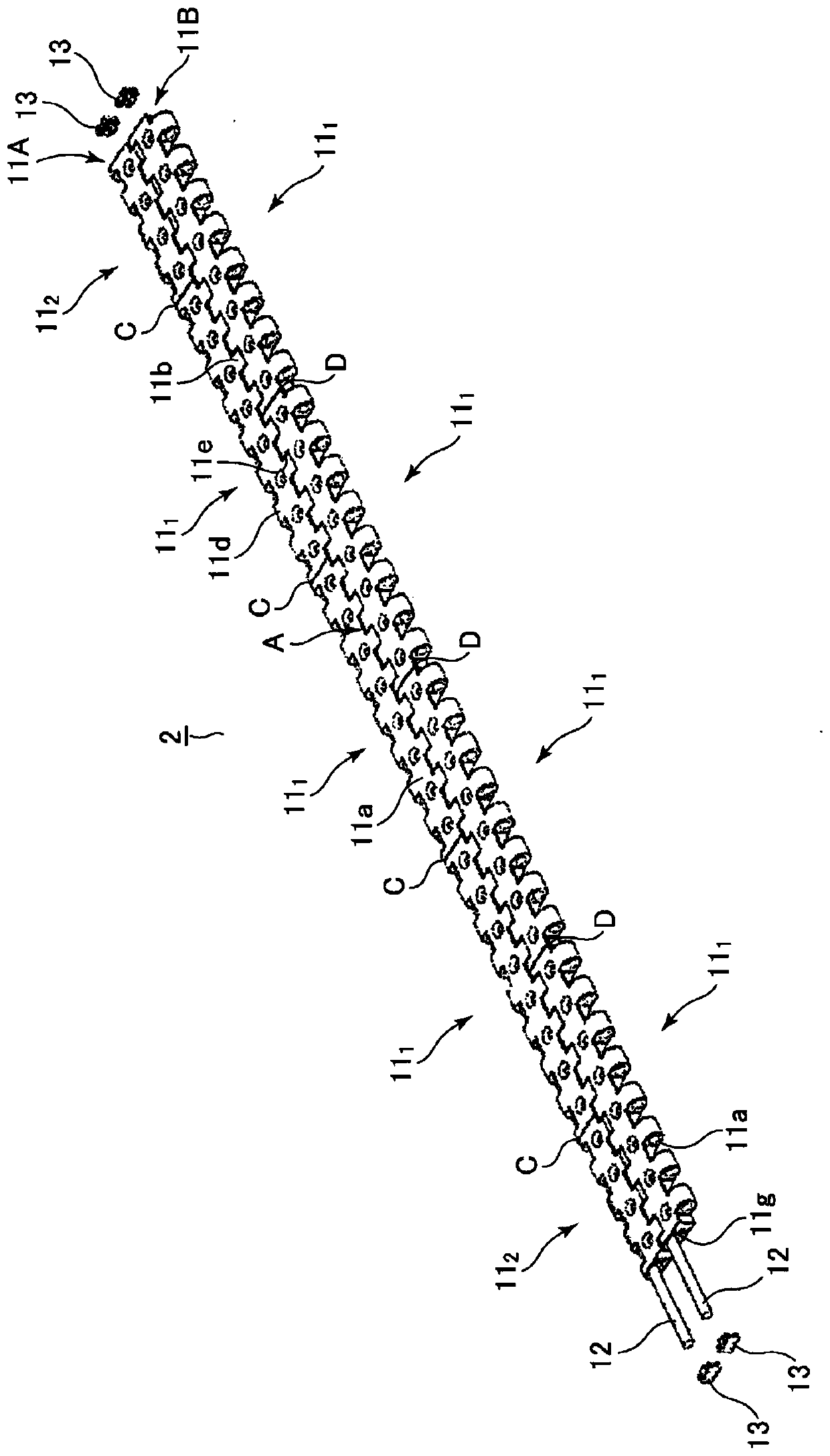
[0037] Hereinafter, embodiments of the present invention will be described with reference to the drawings. Such as figure 1 As shown, in the vacuum conveyor 1 to which the present invention can be applied, an endless chain 2 is guided by a moving guide and wound between sprockets 3 and 5 . In the chain 2 , a plurality of links having a flat mounting surface are flexibly connected, driven by rotation of at least one of the sprockets 3 and 5 , and moved while being guided by a moving guide. Suction chambers (suction units) 6 . A suction device (negative pressure device) 7 ... such as a blower fan communicates with the suction chamber 6 , and the suction chamber 6 is brought into a predetermined negative pressure (low pressure lower than atmospheric pressure) state by the suction device 7 . Each link of the chain 2 is respectively formed with suction holes through which the negative pressure from the above-mentioned suction chamber 6 acts on the object to be conveyed 9 such as...


PUM


Abstract

The present invention overcomes the problem that, in a chain that conveys to-be-conveyed articles via suction through suction holes that pass through a flat mounting surface, the suction force will beinsufficient and stable conveying will be impossible when the suction holes are of a straight form. Suction holes 15 are formed in an endless link 11 by a connection member. The suction holes 15 comprise a taper part 15a having an opening that comprises a large area of an obverse surface A to be the mounting surface, and a straight part 15b by which a reverse-surface B side is connected to the smallest cross-sectional surface area of the taper part.

Description

technical field [0001] The present invention relates to a chain for a vacuum conveyor that conveys conveyed objects such as negative pressure adsorption tanks. Background technique [0002] Conventionally, there is known vacuum conveying in which a chain in which a plurality of links having a flat mounting surface are connected by pins moves on a suction unit, and the conveyed object is sucked and conveyed from suction holes opened on the mounting surface. machine (refer to Patent Documents 1 and 2). The chain for vacuum conveyor can place the bottom surface of cans and plastic bottles on the loading surface, and apply the negative pressure of the above-mentioned suction part to the cans and plastic bottles on the above-mentioned loading surface through the suction holes, so that the cans, etc. Conveying in the way of inclined surface and vertical surface. [0003] In the conveyor of Patent Document 1, through-holes (suction holes) and positioning protrusions of the same d...

Claims


Application Information

Patent Timeline
Patent Type & Authority Applications(China)
IPC IPC(8): B65G17/46B65G17/08
CPCB65G17/08B65G17/46B65G17/28B65G17/38
Inventor 井口隼人泽田大悟
Owner DAIDO KOGYO CO LTD
Learn More