
Transmission with continuous lubrication

A transmission device and driving force technology, applied in the field of transfer case, can solve problems such as ineffectiveness, achieve the effects of small power loss, reliable lubrication, and improved service life

Inactive Publication Date: 2019-10-11
MAGNA POWERTRAIN AG & CO KG
View PDF8 Cites 0 Cited by
  • Summary
  • Abstract
  • Description
  • Claims
  • Application Information

AI Technical Summary

Problems solved by technology

[0003] However, when the torque transmission section is closed in the permanent two-wheel drive mode downstream of the clutch unit in the direction of force by means of a device for closing as described, for example, in document DE 10 2009 005 378 B4 or WO 2014 / 166819 A2 , this type of lubrication is ineffective, wherein a variable fraction of the drive torque can be transmitted to the secondary axle by means of the clutch unit

Method used


Image

  • Transmission with continuous lubrication
  • Transmission with continuous lubrication
  • Transmission with continuous lubrication

Examples


Embodiment Construction

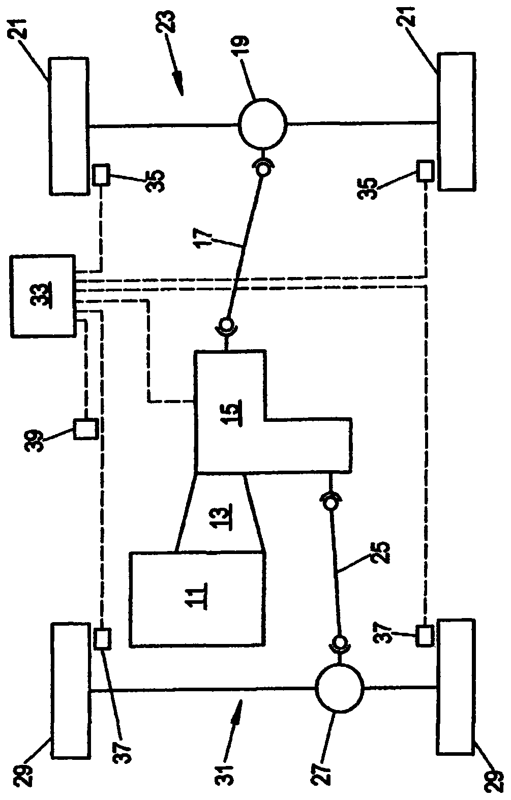
[0020] figure 1 A drive train of a motor vehicle with a switchable all-wheel drive is shown schematically. The drive torque generated by the internal combustion engine 11 is fed to a transfer case 15 via the main transmission 13 (manual shift transmission or automatic transmission). A first output of the transfer case 15 is coupled via a cardan shaft 17 to a rear axle differential 19 . As a result, the wheels 21 of the rear axle 23 are permanently driven. The rear axle 23 thus forms the main axle of the vehicle. The second output of the transfer case 15 is coupled via a cardan shaft 25 to a front axle differential 27 . As a result, part of the drive torque of internal combustion engine 11 can optionally be transmitted to wheels 29 of front axle 31 . The front axle 31 thus forms the secondary axle of the vehicle.

[0021] In addition, in figure 1 The driving dynamics control unit 33 is shown in . The driving dynamics control unit is connected to wheel speed sensors 35 , ...


PUM


Abstract

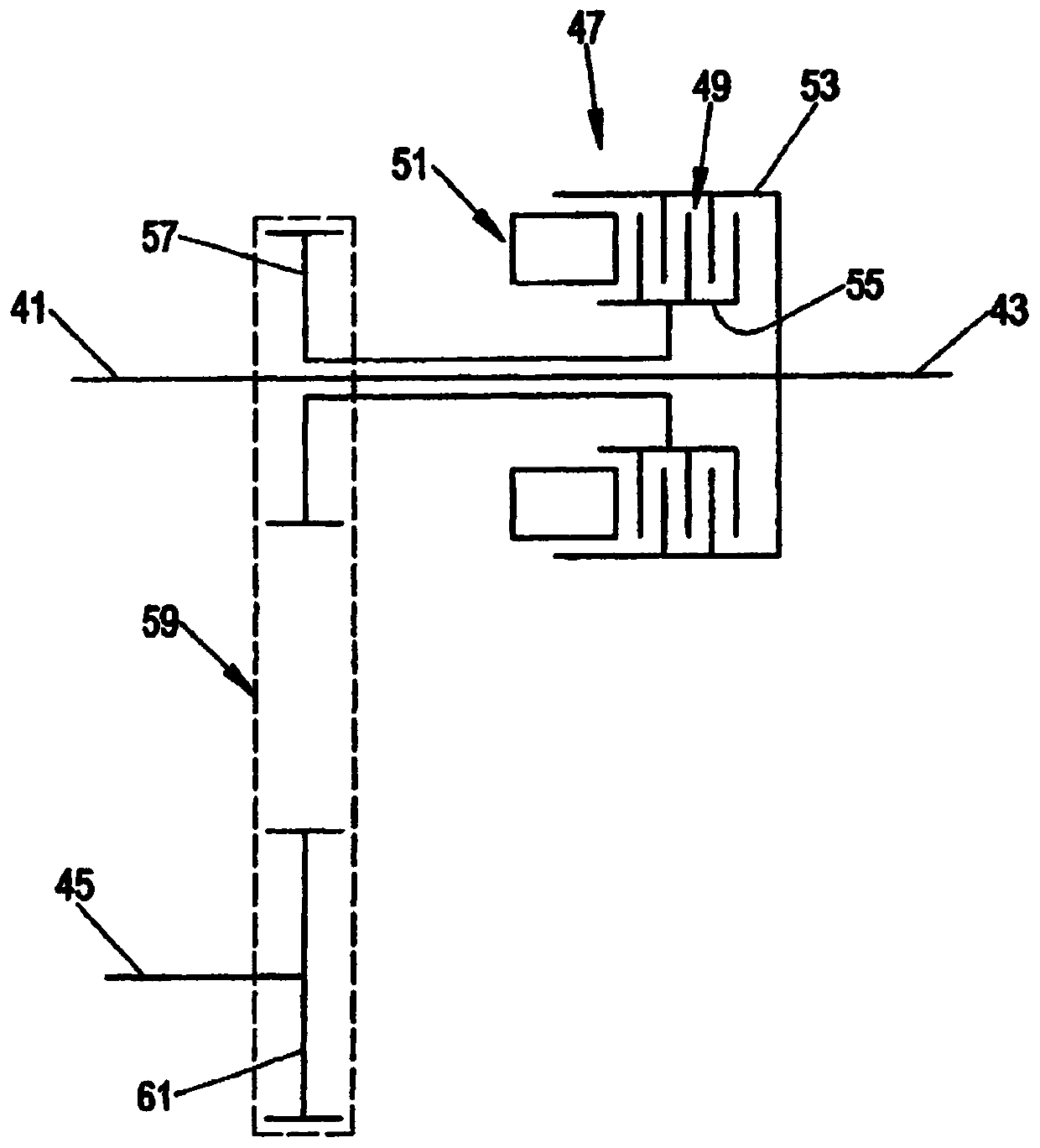
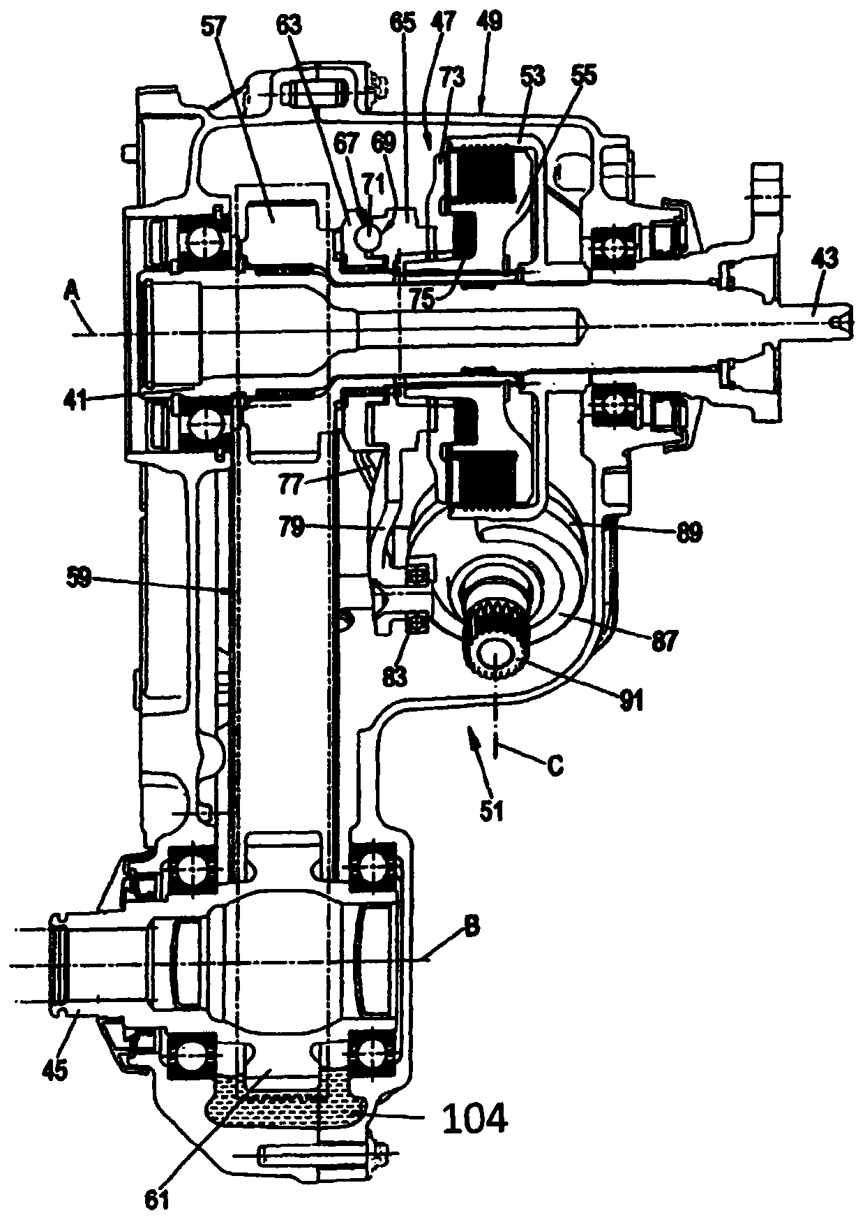
The present invention relates to a transmission comprising an input shaft, a compressor driven by the input shaft, an oil sump and an airlift pump for pumping oil from the oil sump to at least one component of the transmission to be lubricated.

Description

technical field [0001] The invention relates to a transmission and in particular to a transfer case for distributing the drive torque of an input shaft to the main and secondary axles of a motor vehicle as required, said transmission comprising an uninterrupted lubrication system . Background technique [0002] The drive torque can be distributed to several axles of the vehicle as required by means of a transfer case. For this purpose, a clutch unit is used, for example in the transfer case described in DE 10 2008 032 477 A1, by means of which a variable proportion of the drive torque can be transmitted from the input shaft to the auxiliary axle of the vehicle as required. In a so-called "Torque-on-Demand" transfer case, the wheels of the main axle are driven permanently, while a variable fraction of the drive torque can be transmitted to the on the wheels of the sub-axle. Lubrication of the various components of the transfer case can take place by means of passive lubric...

Claims


Application Information

Patent Timeline
IPC IPC(8): F16H57/04F04F1/18F16H57/02
CPCF16H57/0436F16H57/0471F16H57/0472B60K17/351
Inventor 赫贝特·施泰因文德
Owner MAGNA POWERTRAIN AG & CO KG
Learn More